Review and understand mechanical systems
Understand values within a mechanical system and review connector configurations within the family editor.
Tutorial resources
These downloadable resources will be used to complete this tutorial:
Step-by-step guide
Understand values within a mechanical system and review connector configurations within the Family Editor.
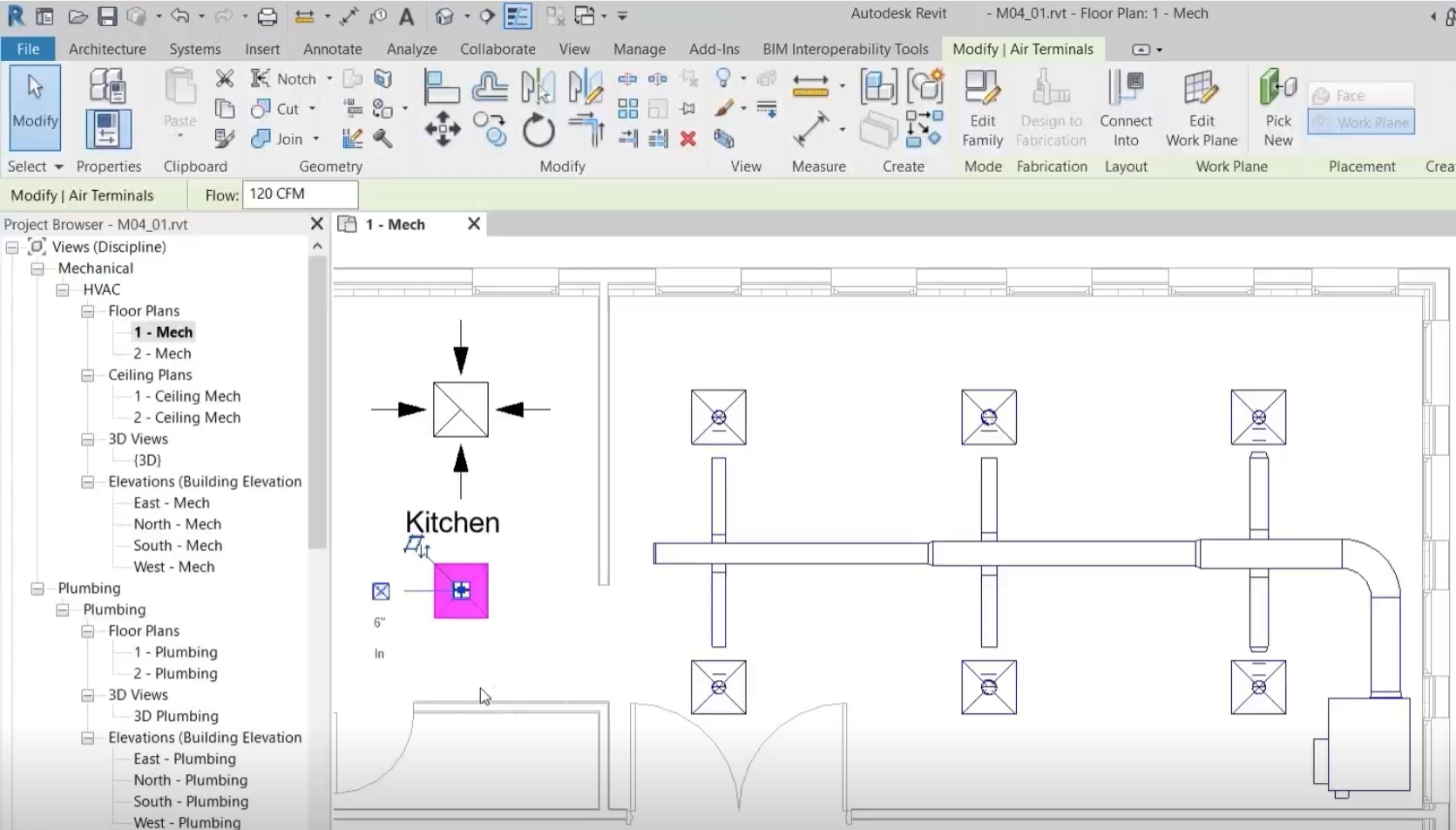
- Open the project M04_01.rvt.
- Ensure that the current view is HVAC > Floor Plans > 1 – Mech.
- Select one of the air terminals in the kitchen as shown.
- Review the Properties of the air terminal to see that it can be connected to a supply air system, the direction of flow at the connector is IN, and the connection size is 6".
- Select the second air terminal in the kitchen.
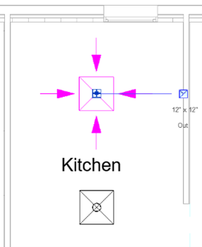
- Review the Properties of the air terminal to see that it can be connected to a return air system, the direction of flow at the connector is OUT, and the connection size is 12" x 12".
- In the completed system next to the kitchen, check the flow rate at each of the air terminals to confirm that the value is 120 CFM.
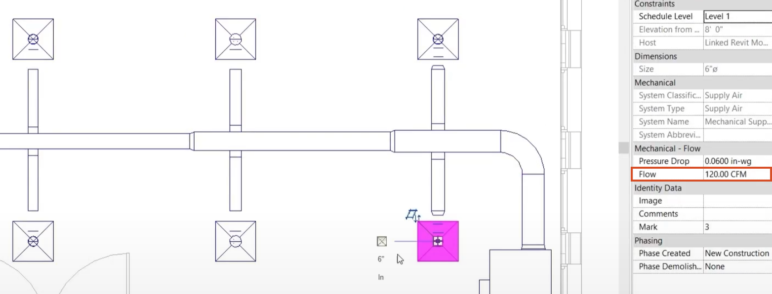
This equates to a total flow rate of 720 CFM.
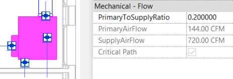
- Select the VAV unit to review its Properties, which show that the total flow rate for all air terminals is calculated at the SupplyAirFlow parameter.
To review the connector configuration of the air terminals in this system:
- Select one of the connectors.
- On the ribbon, click Edit Family.
- On the air terminal family, select the connector.
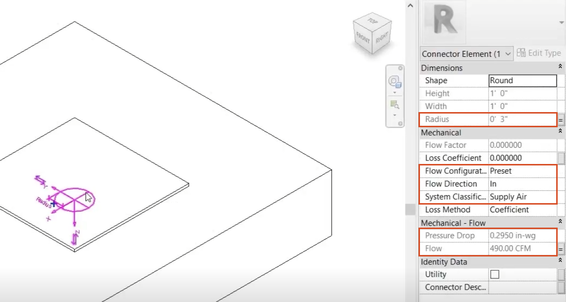
In the Properties palette, note the following:
- The System Classification parameter determines that this air terminal can be connected to a supply air system.
- The Flow Direction is set to IN at the connector, meaning that the air flows into the air terminal.
- The Flow Configuration parameter is set to Preset, meaning that the flow rate will be set by the user from within the project.
- The Radius and Flow parameters are associated to Family Parameters. The values are grayed, which means that their values will be altered when the family is in use in the project.
- For the Radius parameter, at the end of the row, select the equals (=) symbol.
- In the Associate Family Parameter dialog box, notice that the Radius parameter is associated with the Duct Radius parameter.
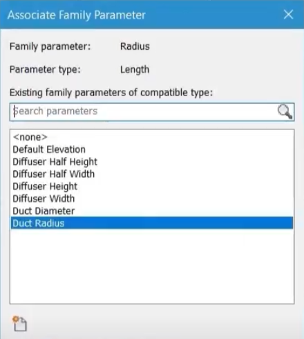
- Click OK to close the dialog box.
- Close the air terminal family without saving.