Conceptual duct and pipe layouts
Understand and create conceptual duct and pipe layouts.
Tutorial resources
These downloadable resources will be used to complete this tutorial:
Step-by-step guide
Understand and create conceptual duct and pipe layouts.
- Open the project M02_01.rvt.
- Ensure that the current view is HVAC > Floor Plans > 1 – Mech.
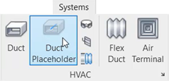
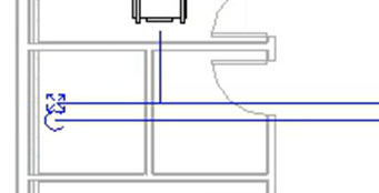
- On the ribbon, Systems tab, HVAC panel, select Duct Placeholder.
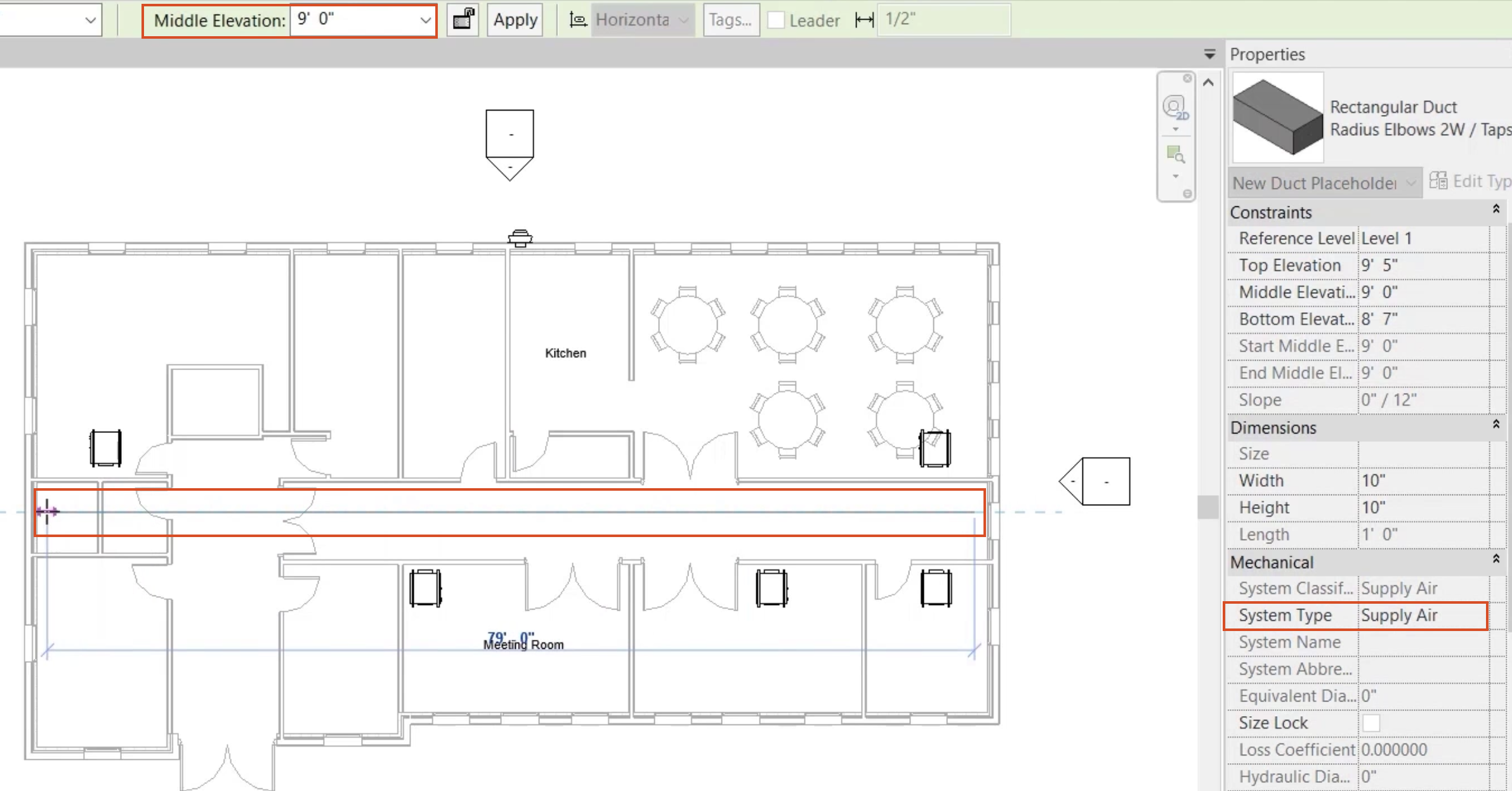
- In the Properties palette, set the System Type to Supply Air.
- On the Options Bar, set the Middle Elevation to 9'.
- Starting at the far-right end of the corridor, draw a duct placeholder just above the center, extending to the riser space at the left end of the building.
- On the Options Bar (or in Properties), change the Middle Elevation to 0.
- Click Apply to complete the main run of duct.
- Set the Middle Elevation back to 9'.
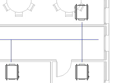
- Draw a Duct Placeholder from the main run out to each of the five fan coil units.
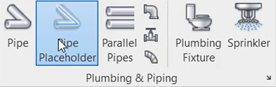
- On the ribbon, Systems tab, Plumbing & Piping panel, select Pipe Placeholder.
- In the Properties palette, set the System Type to CHW-F.
- Set the Middle Elevation to 9'.
- Starting at the right end of the corridor, draw a pipe placeholder just below the duct placeholder, extending to the riser space at the left end of the building.
- On the Options Bar, change the Middle Elevation to 0.
- Click Apply to complete the main run of pipe.
- Use the same method to create a pipe placeholder for CHW-R, changing the middle elevation to 0 at the riser.
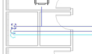
- On the ribbon, select Pipe Placeholder.
- Set the Middle Elevation to 9'.
- Create branches for CHW-F and CHW-R to each of the five fan coil units.
- From the Project Browser, open the default 3D view to review the finished example.
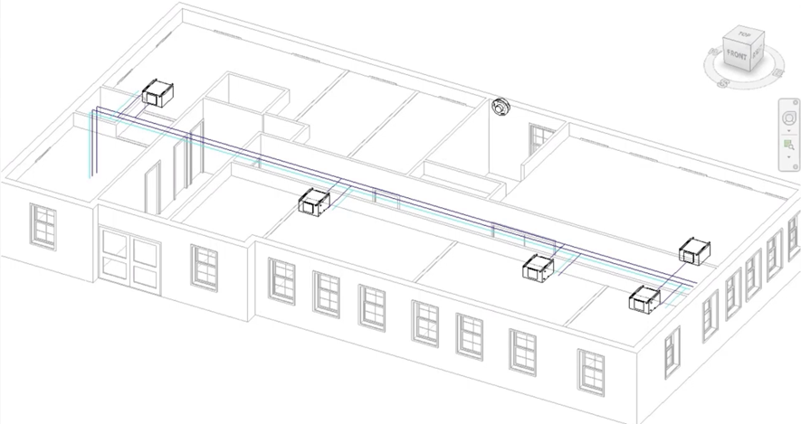
- Save the project.