Creating and editing ducting and piping systems
Review existing and create new duct and piping systems.
Tutorial resources
These downloadable resources will be used to complete this tutorial:
Step-by-step guide
Review existing and create new duct and piping systems.
- Open the project M01_03.rvt.
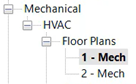
- Ensure that the current view is HVAC > Floor Plans > 1 – Mech.
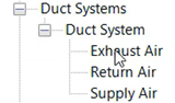
- In the Project Browser, review the existing duct systems in this project by expanding Families > Duct Systems > Duct System.
Existing systems for Exhaust, Return, and Supply Air can be viewed here.
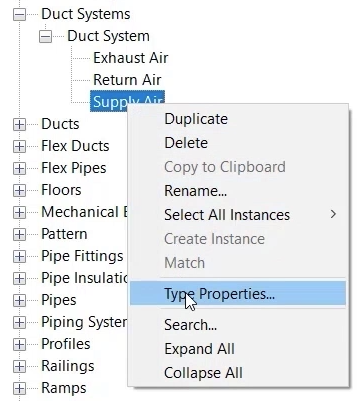
- Right-click Supply Air and select Type Properties to review its properties.
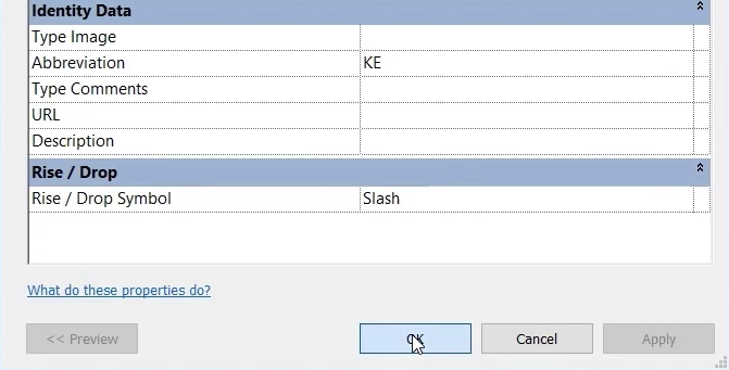
- In the Type Properties dialog box, note the options to apply graphics overrides, change materials, and set calculation methods, as well as to apply a system abbreviation and description.
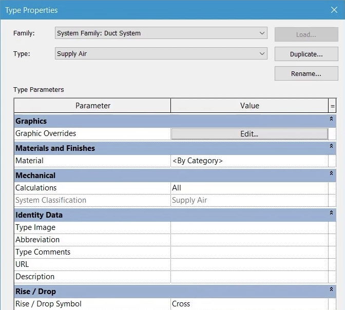
- Click OK to close the dialog box.
- Follow the same steps to review the system properties for Hydronic Supply, noting the addition of Fluid Type and Fluid Temperature.
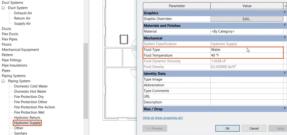
- Click OK.
- To create a new Duct System, right-click an existing system—here, the Exhaust Air system—and select Duplicate.
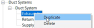
- Rename the duplicated system to “Kitchen Extract”.
- Right-click Kitchen Extract and select Type Properties.
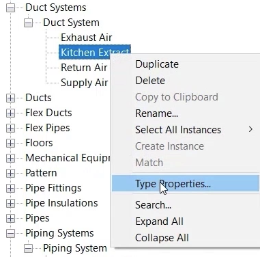
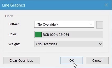
- In the Type Properties dialog box, next to Graphics Overrides, click Edit.
- In the Line Graphics dialog box, change the Color to a different shade of green.
- Click OK.
Note: materials can also be applied, and the calculation option set to improve the performance of larger Revit models.
- In the Abbreviation field, type "KE" (Kitchen Extract).
- Click OK to close the dialog box.