Work with Revit spaces and system data
Review design values in a space.
Tutorial resources
These downloadable resources will be used to complete this tutorial:
Step-by-step guide
Review design values in a space.
- Open the project M05_03.rvt.
- Ensure that the current view is HVAC > Floor Plans > 1 – Mech System Data.
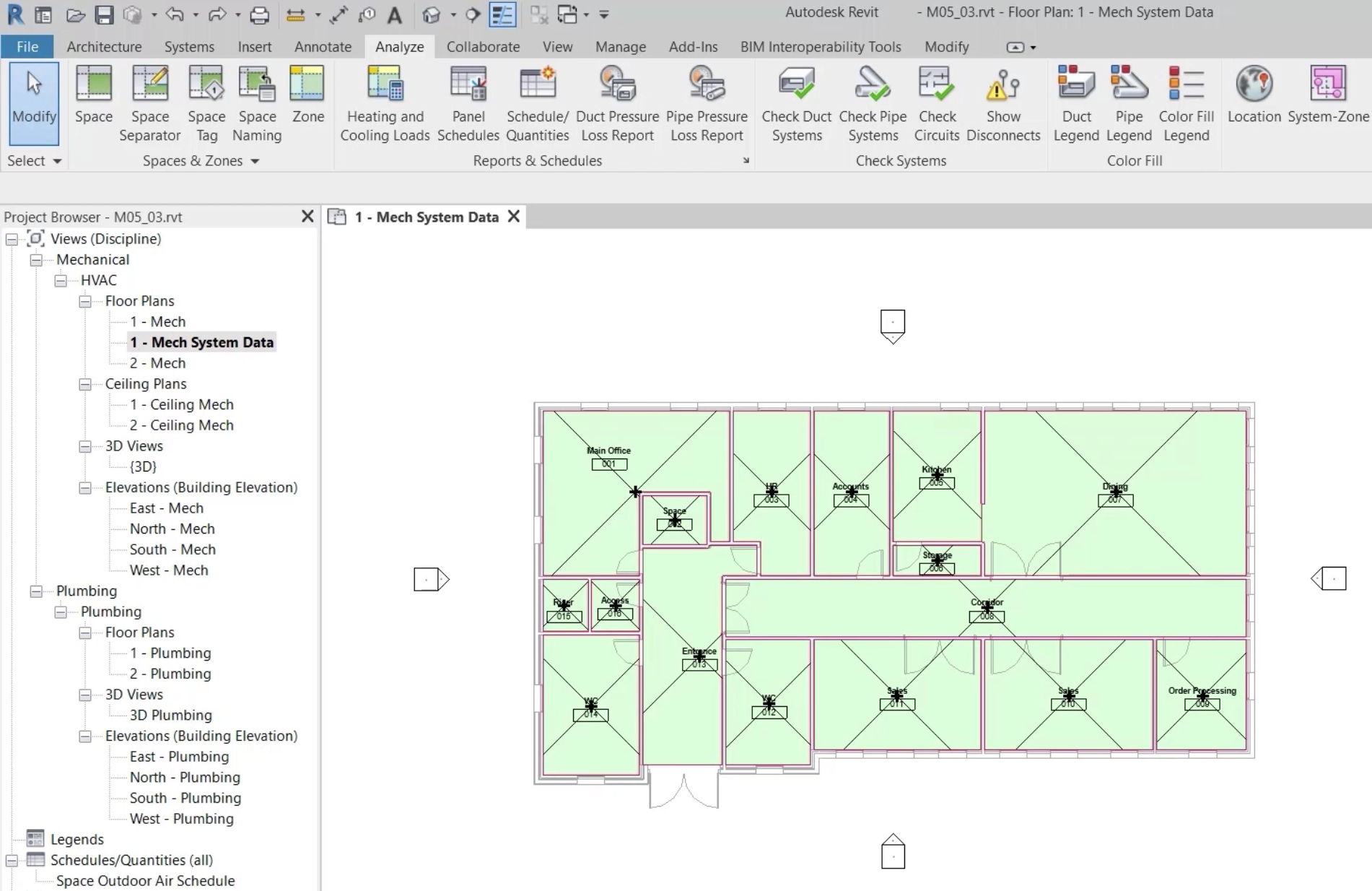
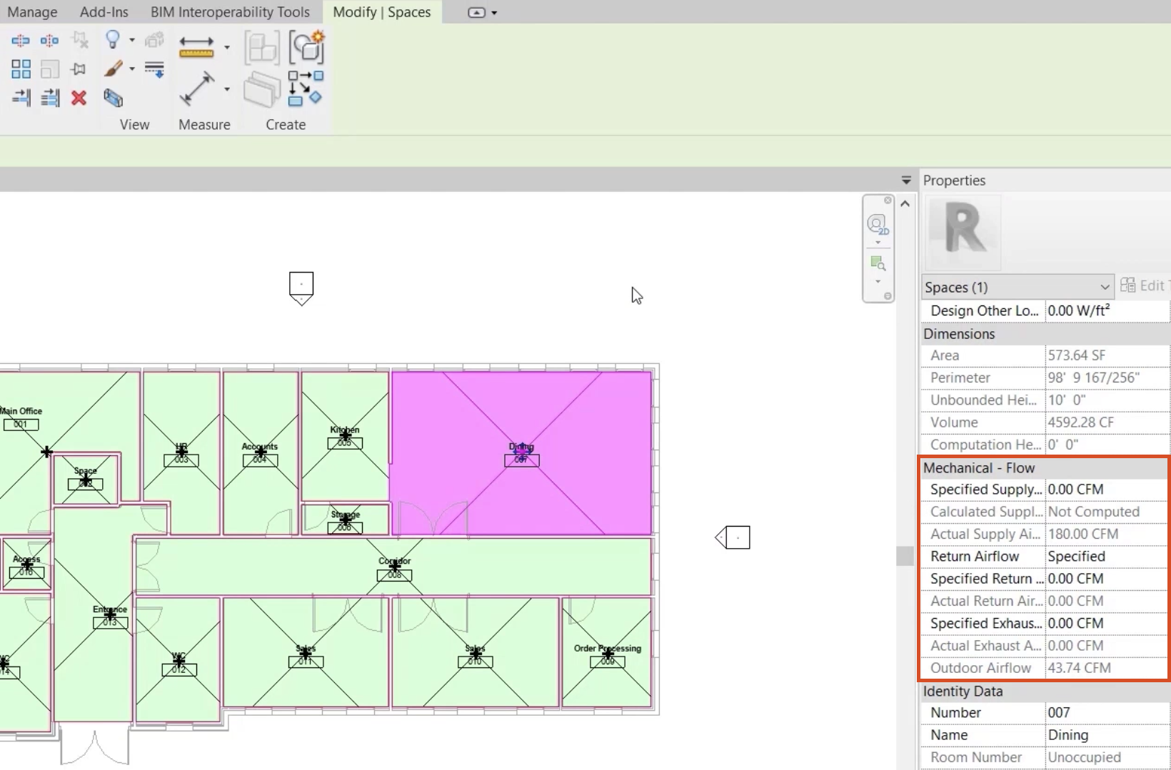
- Select the space Dining 007.
- In the Properties palette, review the current Mechanical Flow properties, based on the systems located within the space.
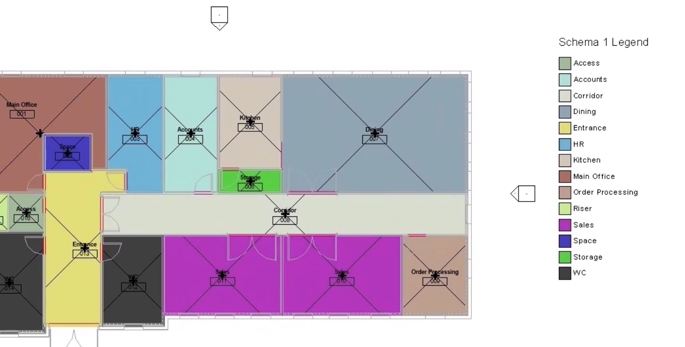
To visualize the mechanical flow properties in each space, create a color fill legend.
- Click a blank area in the view to deselect the dining space.
- On the ribbon, Analyze tab, Color Fill panel, click Color Fill Legend.
- Click to place the legend to the right of the floor plan, moving the view if necessary.
- Click OK to accept the defaults.

The default scheme displays the space names.
To change the display of the scheme:
- Select the legend.
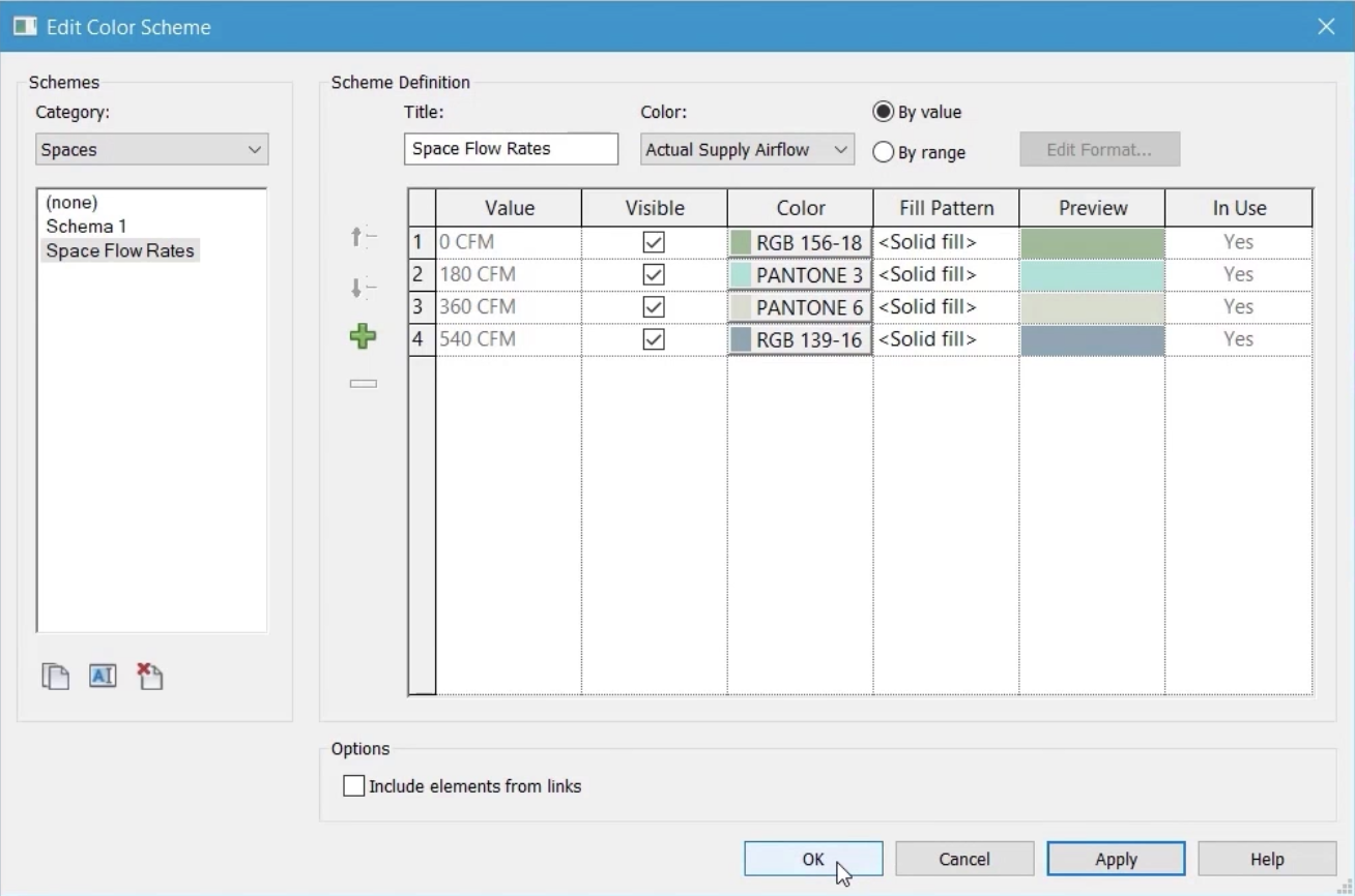
- From the ribbon, click Edit Scheme.
- In the Edit Color Scheme dialog box, click the Duplicate icon to create a copy of the existing scheme.
- Name the new color scheme "Space Flow Rates".
- Click OK.
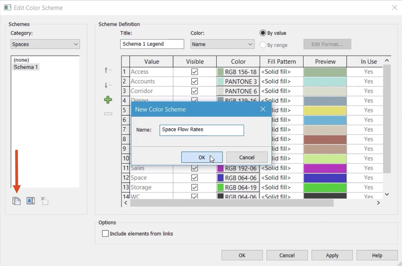
- In the Title field, rename the scheme to "Space Flow Rates".
- From the Color drop-down, select Actual Supply Airflow.
- In the Colors Not Preserved confirmation popup, click OK.
- Ensure that the scheme definition is set to By value.
- Click OK.
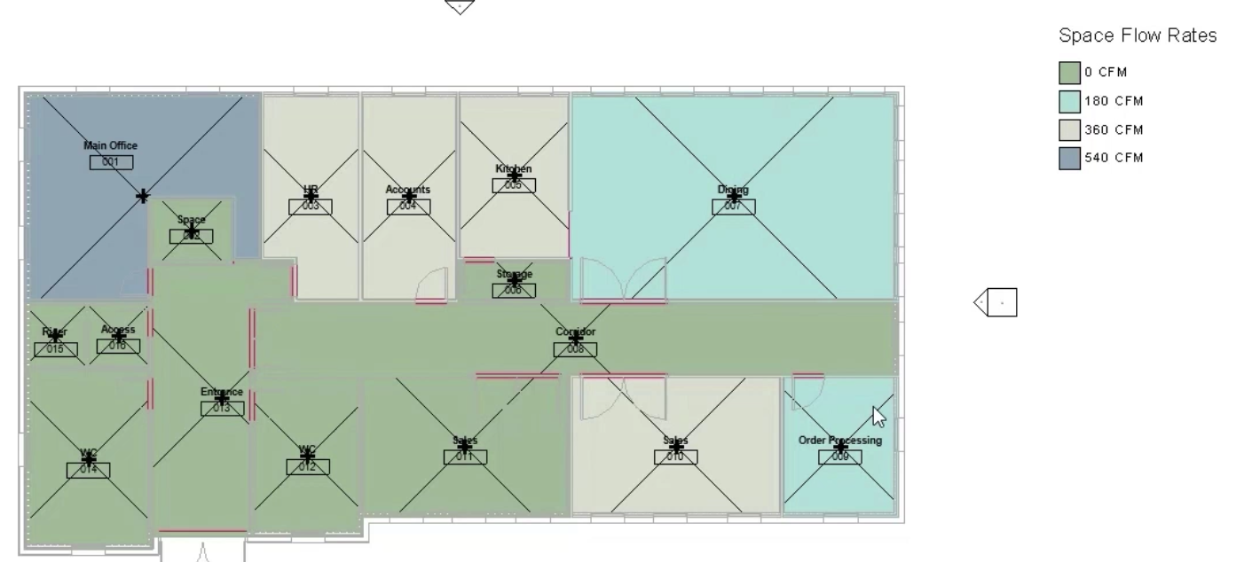
The revised scheme clearly shows the flow rates in each area, including the areas where there is currently no airflow. Note that the dining area and the office for order processing have the same flow rate.
- Open the floor plan 1 – Mech.
- Select any one of the air terminals in the dining area.
- Review the flow rate. Each air terminal is set to 30 CFM.
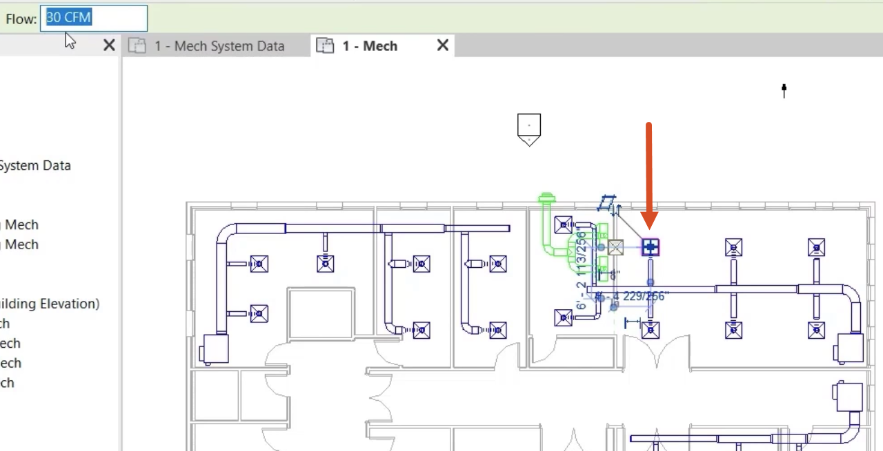
- Select all the air terminals in the dining area.
- Set the flow rate to 200 CFM.
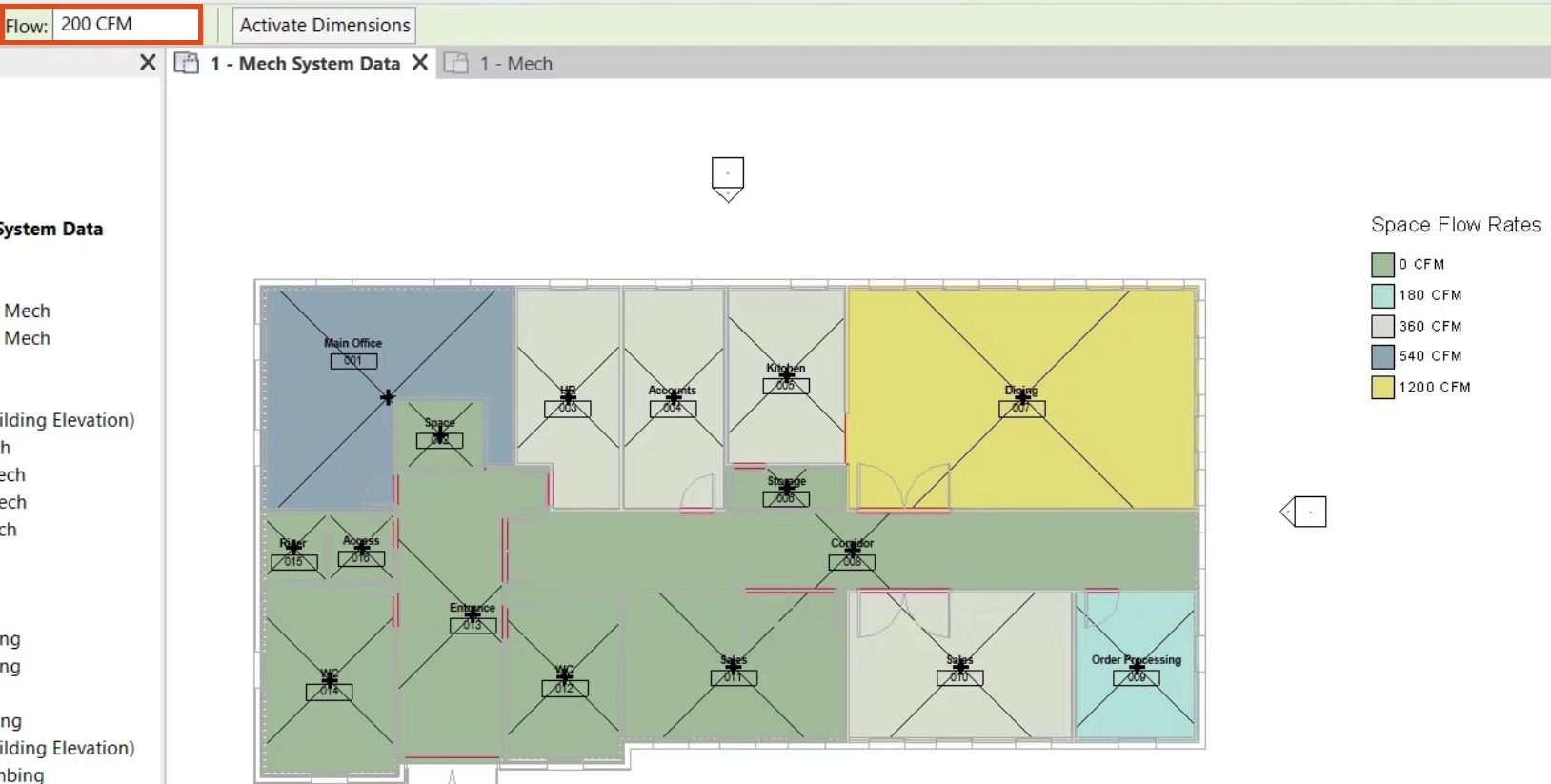
The increased airflow rate to the dining area is shown in the updated floor plan and legend.
- Select the legend.
- Click Edit Scheme.
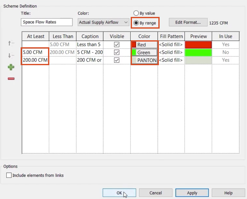
- In the Edit Color Scheme dialog box, change the Scheme Definition to By range.
- Set the At Least value to 5 CFM.
- To add another value to the At Least column, click Add Value (+).
- Change the new value to 200 CFM.
- In the Color column, one at a time, select each of the colors to change it.
- Click OK to close the dialog box.
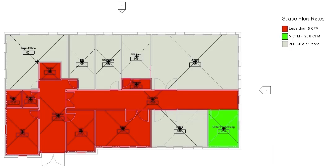
The updated floor plan displays the airflow ranges set in the edited legend scheme.
- Save the project.