Work with check system tools
Review system check tools and use them to highlight system errors.
Tutorial resources
These downloadable resources will be used to complete this tutorial:
Step-by-step guide
Review system check tools and use them to highlight system errors.
- Open the project M06_01.rvt.
- Ensure that the current view is HVAC > Floor Plans > 1 – Mech.
- On the ribbon, Analyze tab, note the Check Systems panel and tools.

- Click Show Disconnects.
- In the Show Disconnects Options popup, select Duct and Pipe.
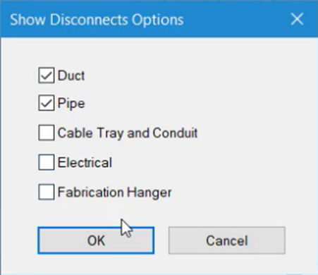
- Click OK.
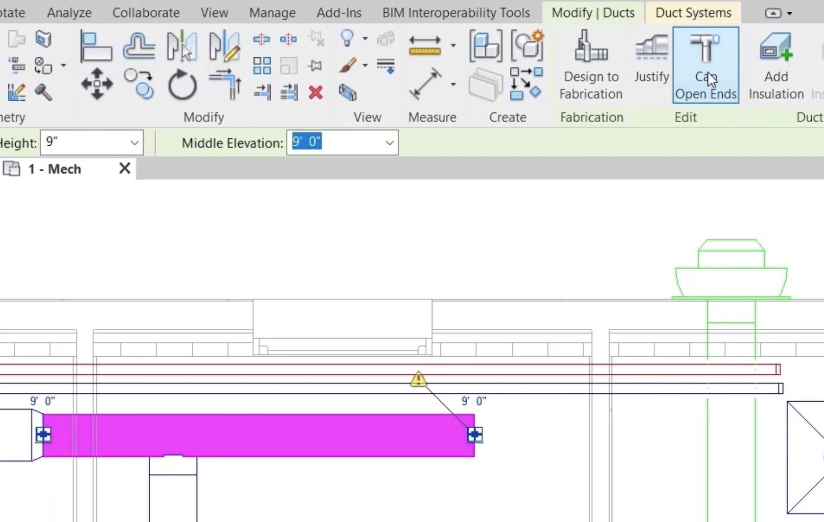
Disconnects are indicated by a yellow warning triangle.
- Select the section of duct with the disconnect.
- On the contextual ribbon tab, click Cap Open Ends to resolve the issue.
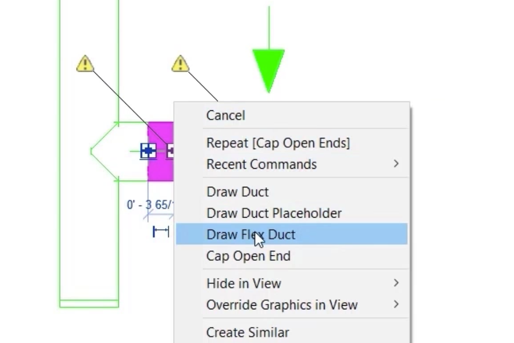
- To recreate the connection to the air terminal, right-click and select Draw Flex Duct.
- Click Show Disconnects.
- Deselect Duct and Pipe.
- Click OK.
- In the Check Systems panel, click Check Duct Systems.
This highlights the issues as shown.
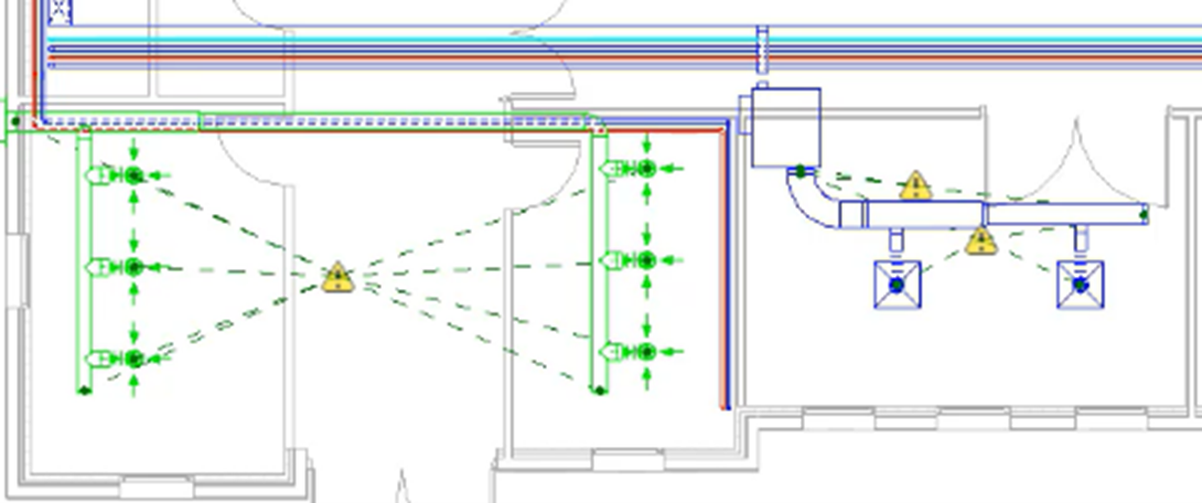
- In the supply system to the right, select the first warning triangle.
- Review the warning message, which suggests an issue with the flow configuration set at the system connectors.
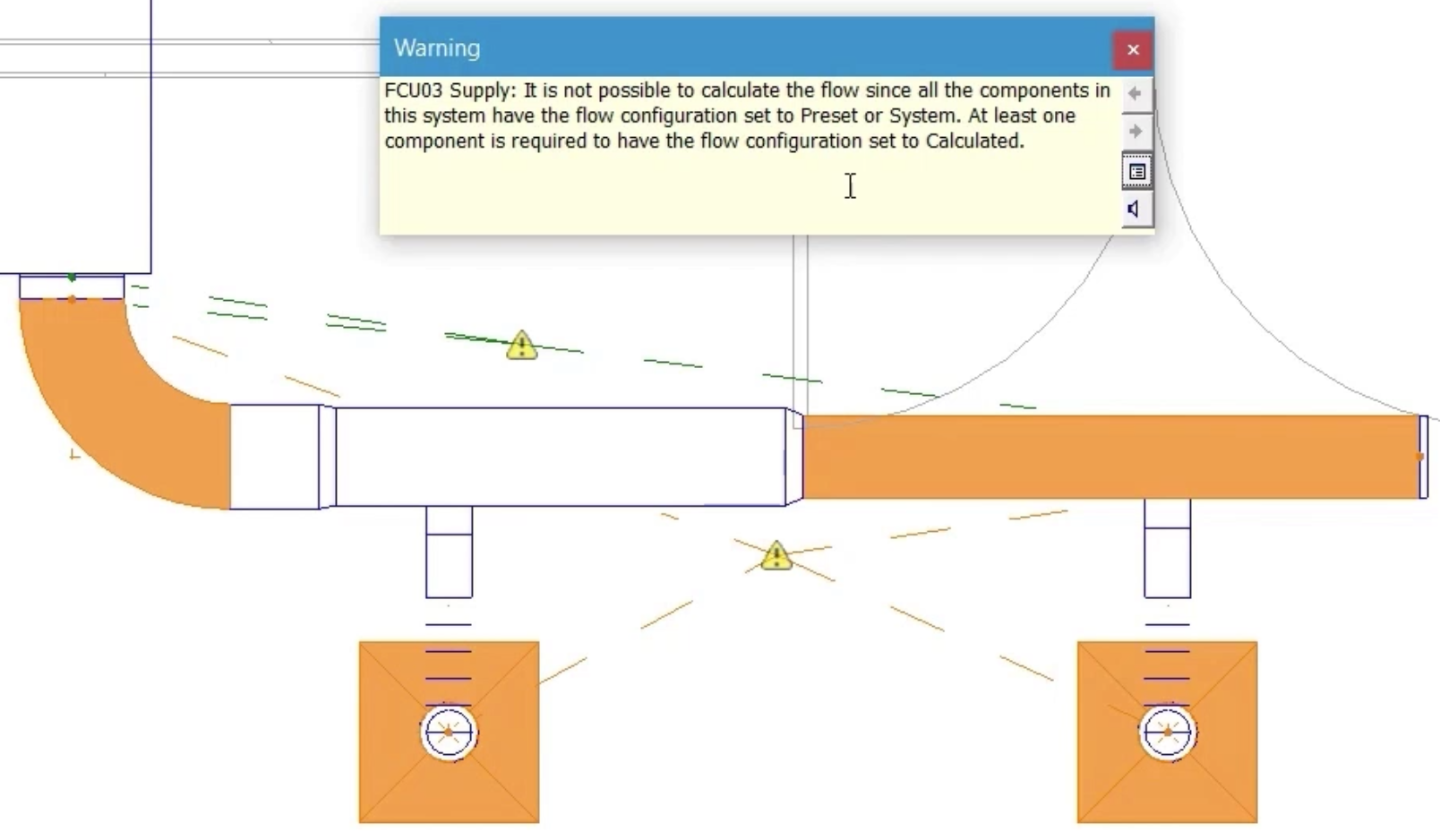
- Close the warning.
- Select the second warning triangle in the system to review the warning that there are disconnects in the system, and that there is more than one physical network.
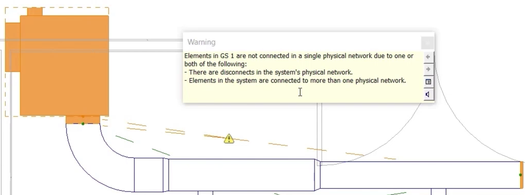
- Close the warning.
- Consider the first warning. The same VAV box and the same air terminals are used in other systems in the project, so the issue is not likely to be with connector configurations.
- Consider the second warning. It is already established that there are no disconnects in the system, so the issue must be that there is more than one physical network.
- Select a section of duct to see that the System Name in Properties is FCU03 Supply.
- Select the VAV unit to see that the System Name is GS 1.
The VAV unit needs to be removed from the system GS 1.
- Position the cursor over the VAV unit and press the TAB key repeatedly until the system is highlighted as shown.
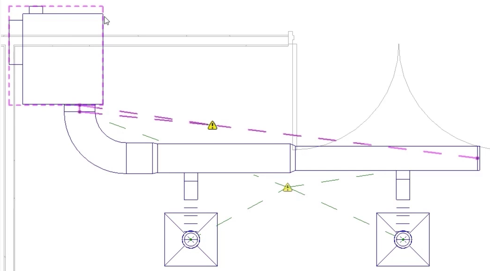
- Select the system with the left mouse button, and then press Delete.
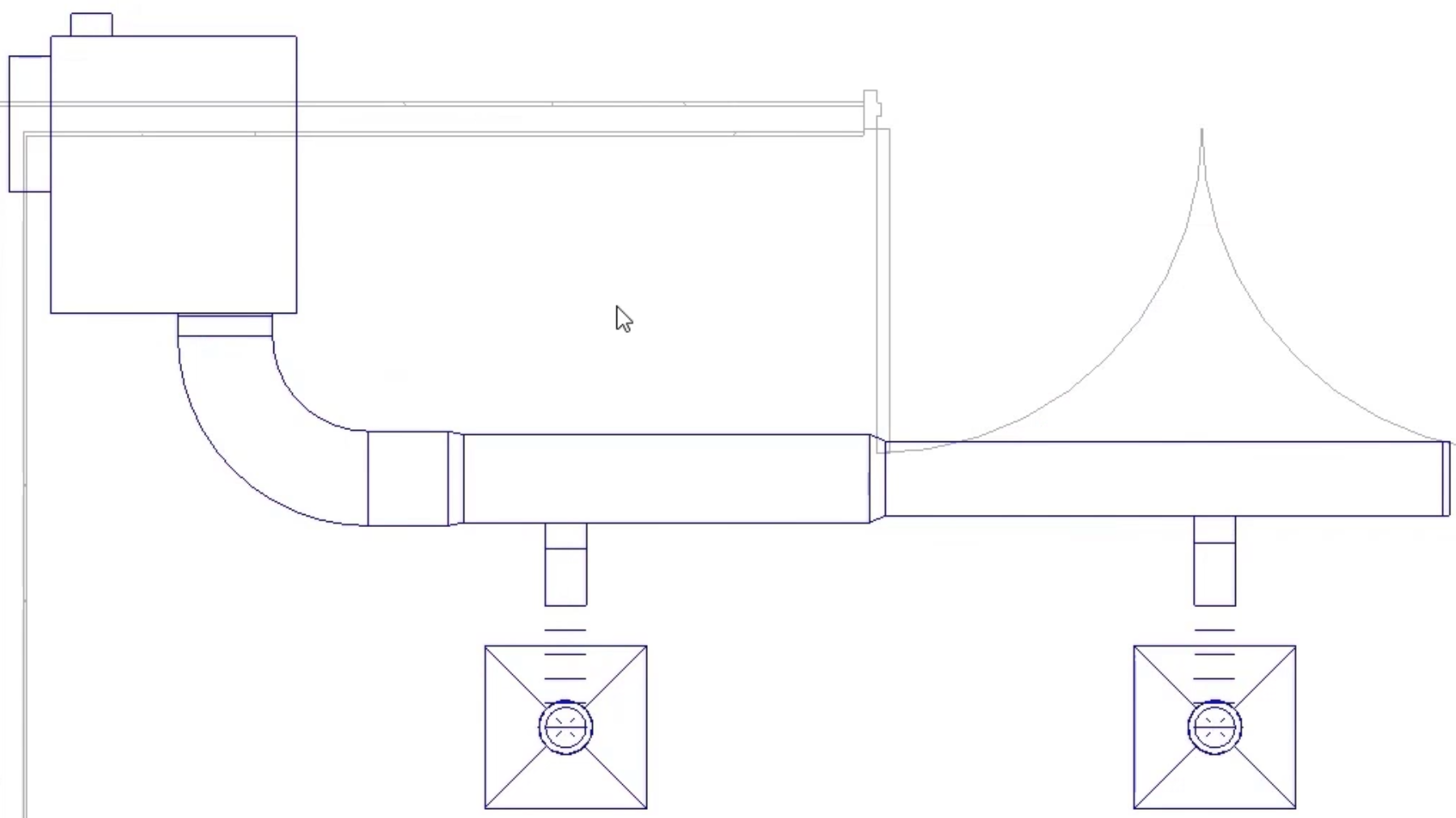
The issue has been resolved, and the warnings disappear.
- Select the warning triangle on the ventilation system to see that there is a flow direction mismatch, and the recommendation is to check the flow direction on all equipment in the system.
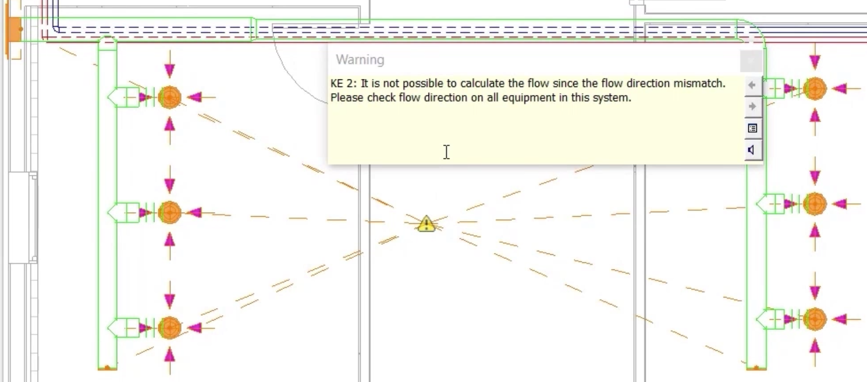
- Close the warning.
- Select the extract grille.
- Click Edit Family.
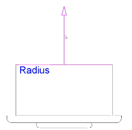
- In the Family Editor, select the system connector.
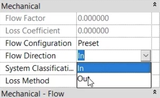
- In Properties, note the Flow Direction, which is set to In. For an extract grille, the flow direction should be set to Out.
- Change the flow direction to Out.
- Click Load into Project.
- Select Overwrite the existing version.
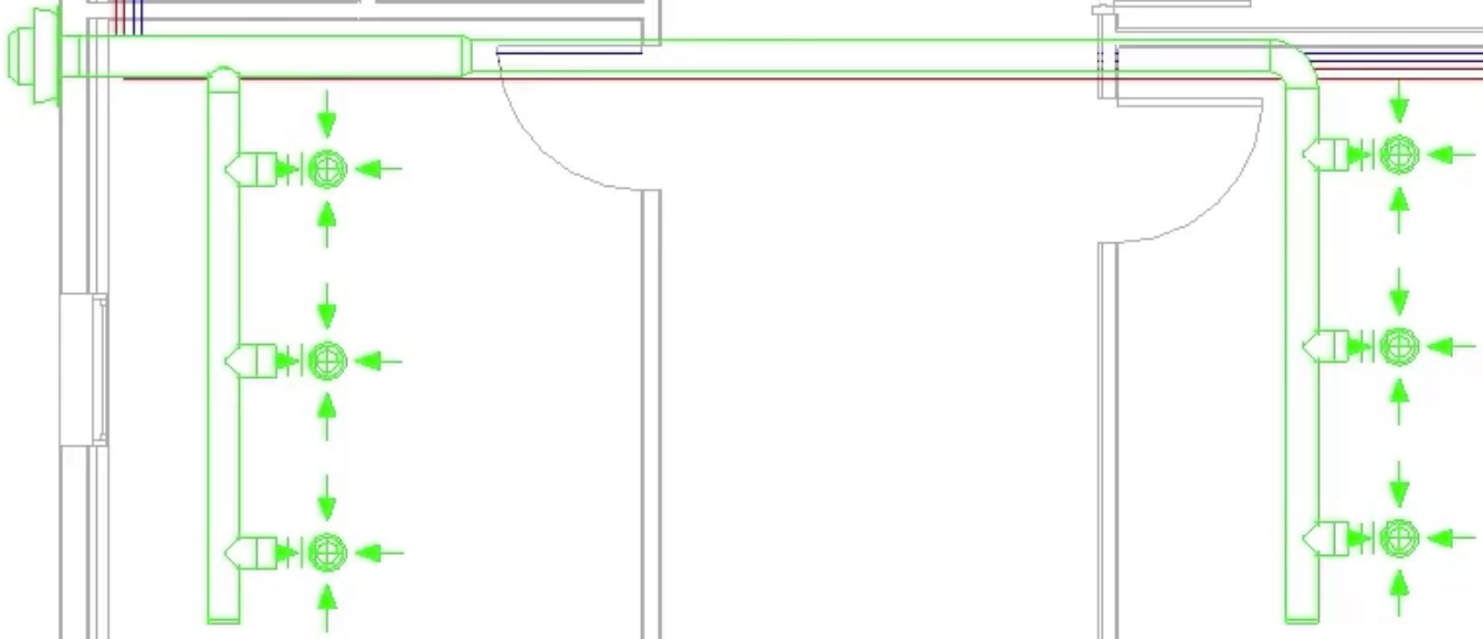
The change to the connector configuration in the family has resolved the issue, and the warning has disappeared.
- Save the project.