Create piping systems with analytical connections
Create a piping system with physical connections and review connection properties.
Tutorial resources
These downloadable resources will be used to complete this tutorial:
Step-by-step guide
Create a piping system with physical connections and review connection properties.
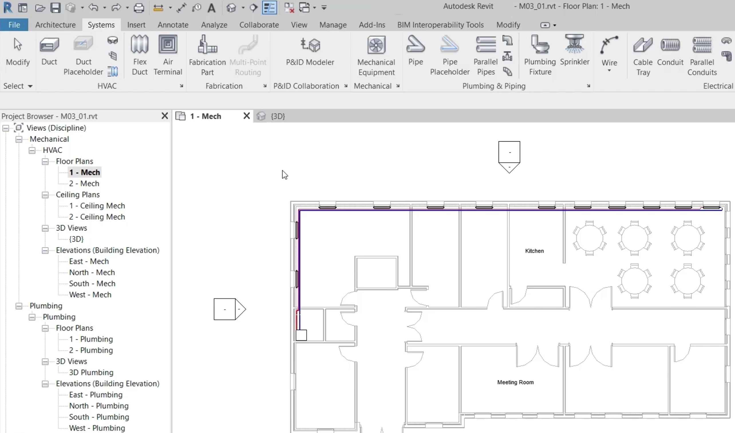
- Open the project M03_01.rvt.
- Ensure that the current view is HVAC > Floor Plans > 1 – Mech.
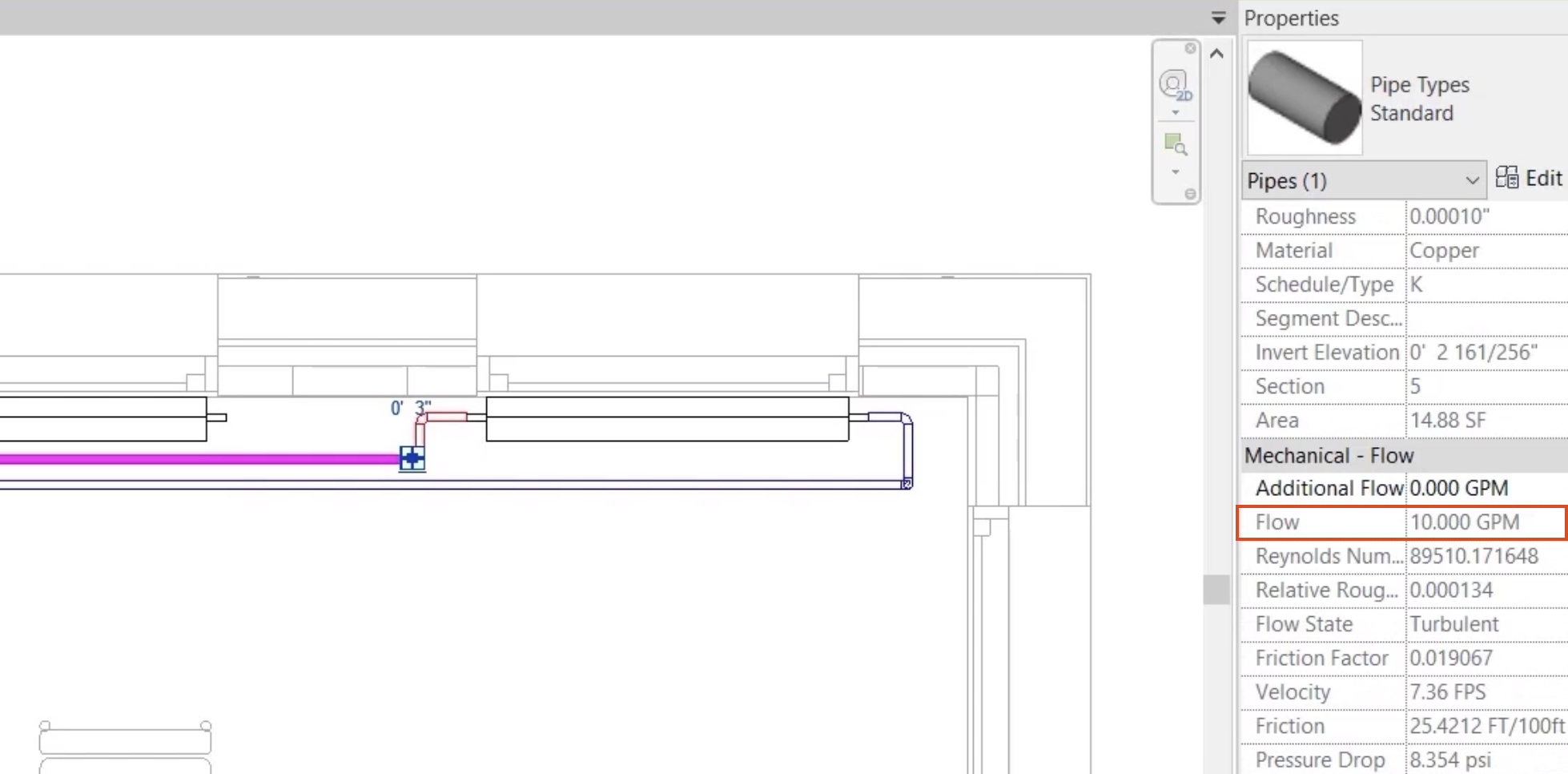
- Select the heating flow and return pipes at the last radiator in the system to review the mechanical flow properties, which show 10 GPM based on a single radiator connected to the system.
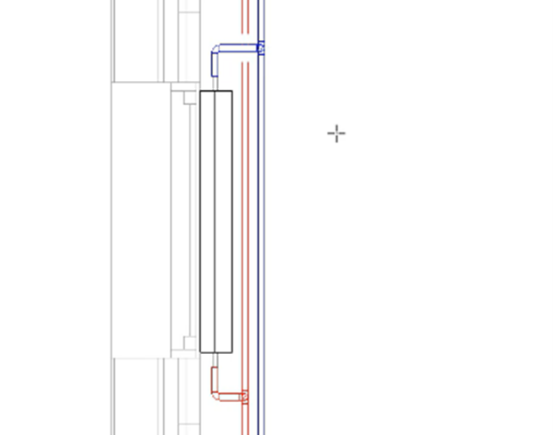
- Using standard modeling techniques, connect the first radiator in the system to the heating flow and return pipes. The system names are HTG-F and HTG-R, and the connection height at the radiator is 18".
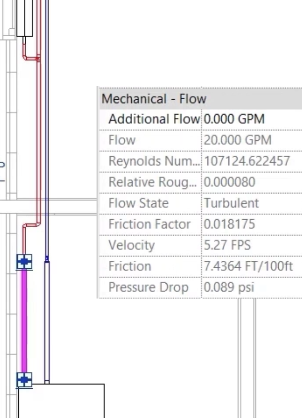
- Select the heating flow pipe at the boiler to review the mechanical flow properties, which have changed with the addition of a second radiator to the system, connected through conventional means.
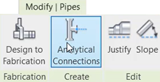
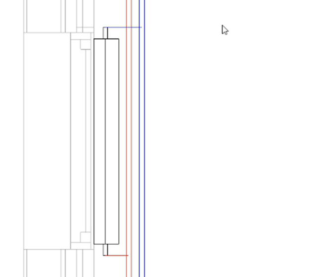
- To add an analytical connection, select the heating flow pipe at the second radiator in the system.
- From the contextual ribbon tab, select Analytical Connections.
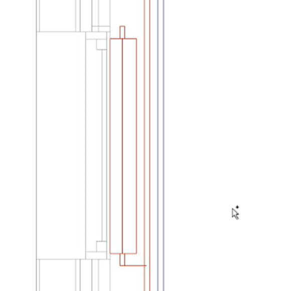
- Select the second radiator, noting the addition of the analytical connection and the change in color to red.
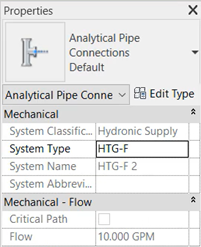
- Select the analytical pipe connection and review the instance properties, which show the flow rate based on the value attributed to the radiator.
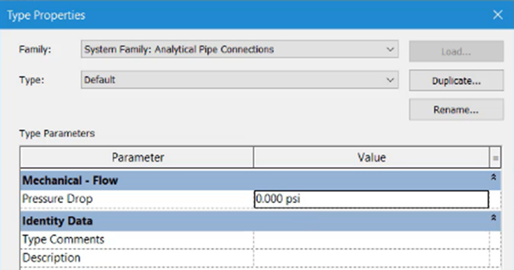
- Access the analytical connection Type Properties to reveal additional information, including pressure drop.
- Using the same technique, connect the heating return pipe to the second radiator in the system.
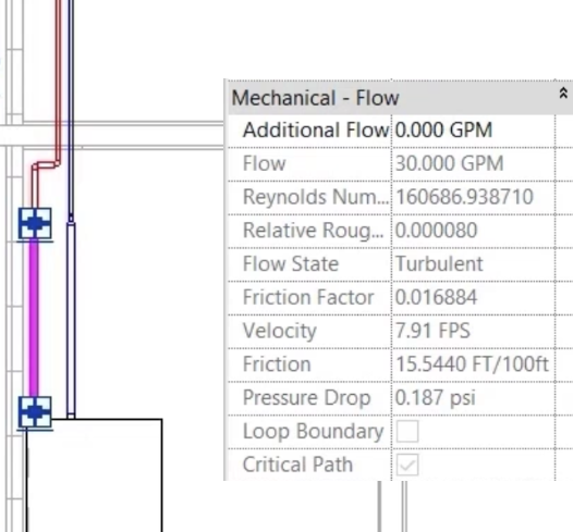
- Select the heating flow pipe at the boiler to review the mechanical flow properties, which have changed again with the addition of the third radiator to the system, connected this time using analytical connections.
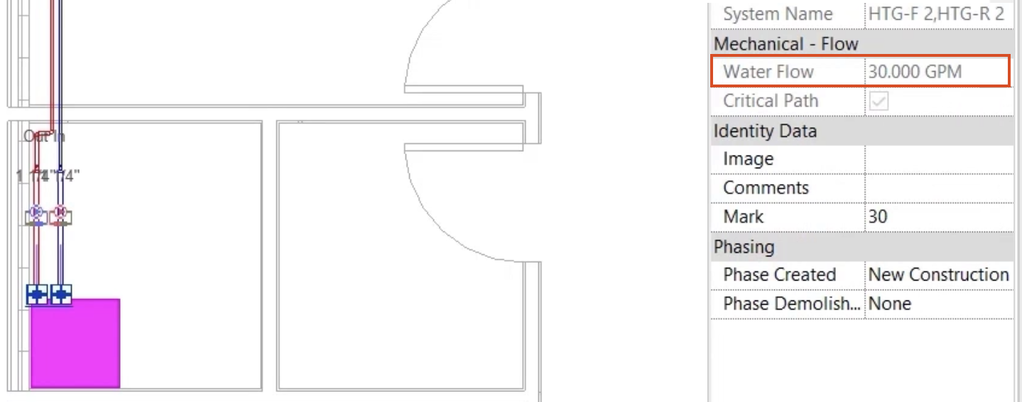
- Select the boiler and note the total water flow in the system: a total of 30 GPM from the three radiators currently connected to the system.
Complete the system using analytical connections:
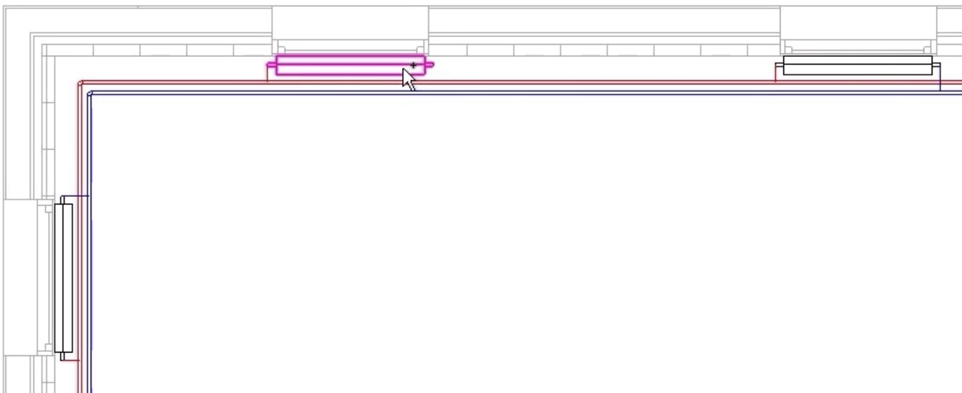
- Select the heating flow pipe.
- Click Analytical Connections.
- Select each of the remaining radiators in turn until the flow side of each one is connected.
- Repeat the process by selecting the heating return pipe and adding analytical connections to the return side of each radiator.
- Save the project.