Create hydraulic separation
Understand closed loop hydronic systems and create hydraulic separation.
Tutorial resources
These downloadable resources will be used to complete this tutorial:
Step-by-step guide
Understand closed loop hydronic systems and create hydraulic separation.
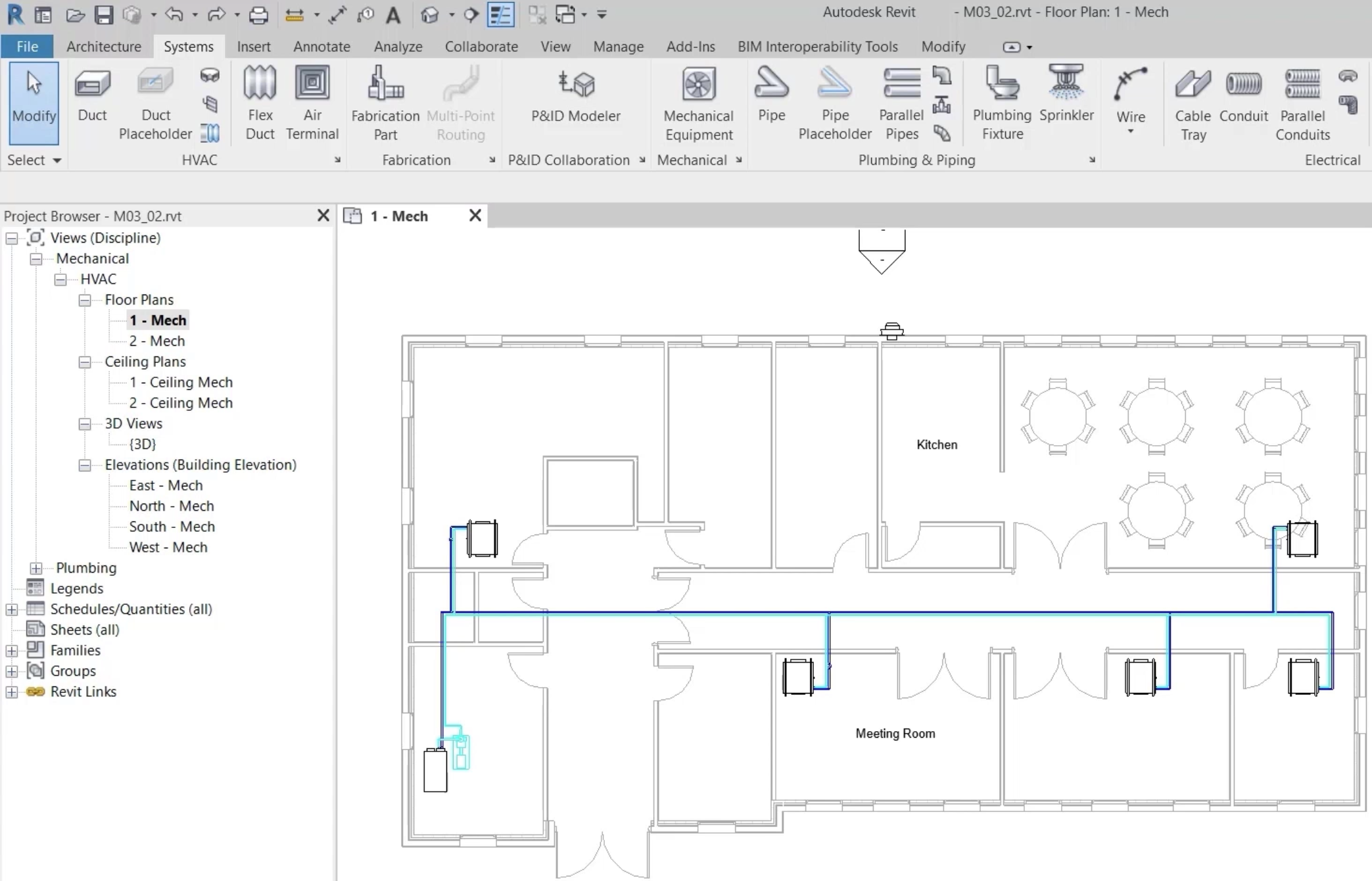
- Open the project M03_02.rvt.
- Ensure that the current view is HVAC > Floor Plans > 1 – Mech.
- On the ribbon, Systems tab, HVAC panel, click the dialog box launcher to open the Mechanical Settings.
- With Calculation selected under Pipe Settings, on the Hydronic Networks tab, review the information shown to understand the criteria for a closed loop hydronic piping network.
- Ensure that Enable analysis for closed loop hydronic piping networks is selected.
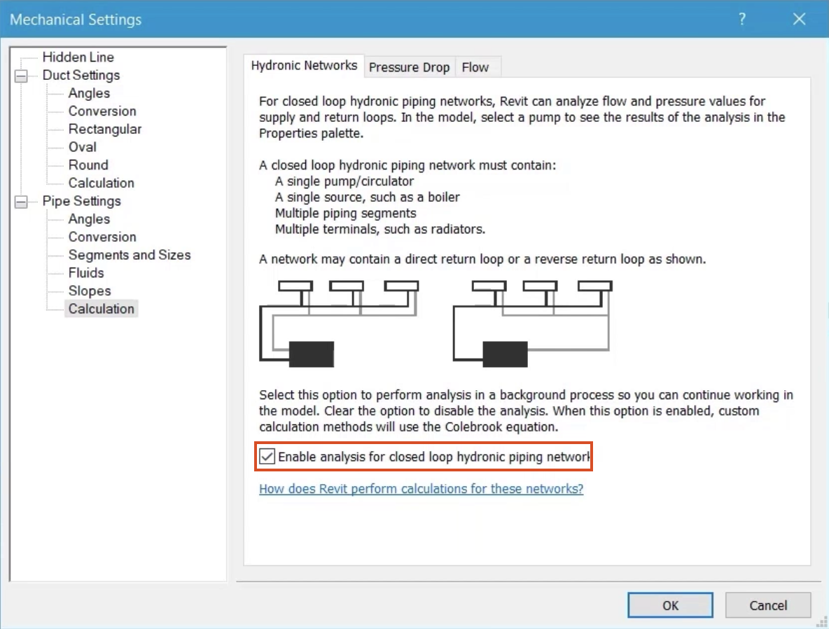
- Click OK.
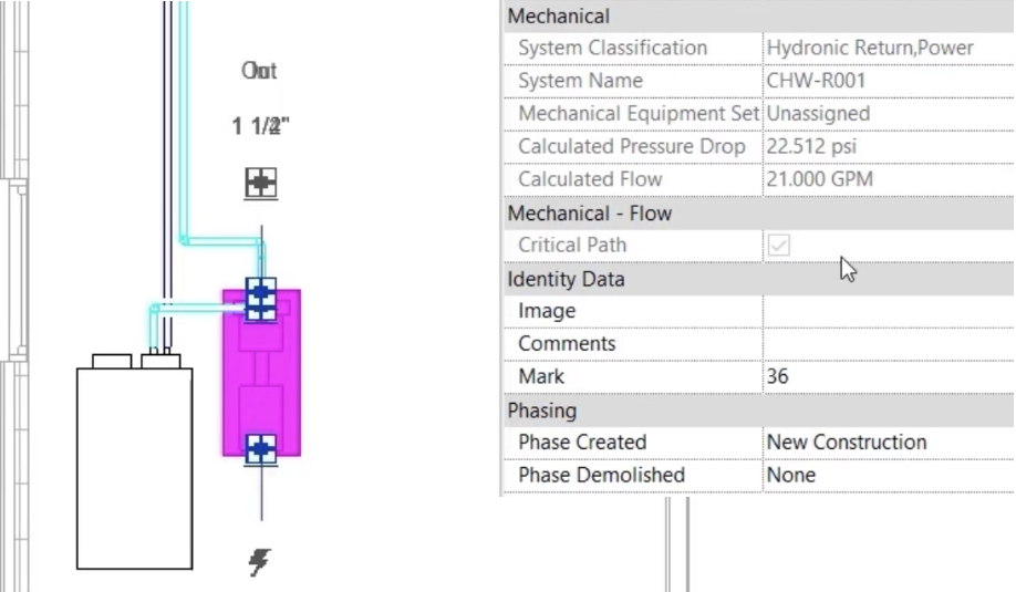
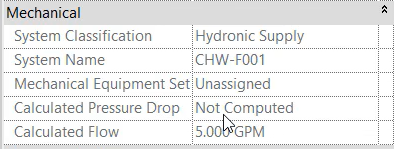
- Select the pump located next to the chiller and review the mechanical properties, which show the values for this entire closed loop hydronic piping network.
- Select any of the flow or return pipes in the network to review the system names, CHW-F001 and CHW-R001.
- With any of the flow or return pipes selected, on the contextual ribbon tab, click System Inspector.
- In the System Inspector, click Inspect.
- In the floor plan, observe that the loops to each fan coil unit are part of the same physical system.
- Select the inline pump in the first loop, and note that not all mechanical flow information is available, as this loop is still part of the larger closed loop hydronic network.
To achieve hydraulic separation of this loop:
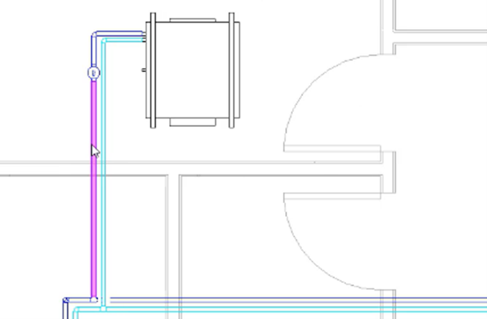
- Select the flow and return pipes as shown.
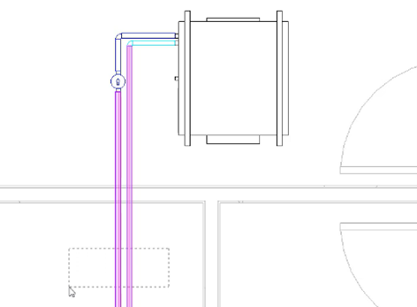
- From the ribbon, select Add Separation. This will cause the loop to become analytically separated from the rest of the system, but it will remain physically connected.
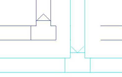
Arrow symbols indicating flow and return appear at the point of separation of the loop if separation is successful.
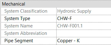
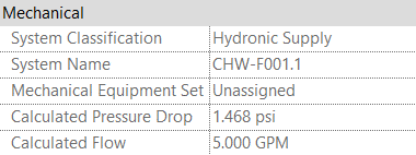
- Select a section of pipe in the separated loop.
- Review the system name, which is the original system name, with a period and a sequential number appended—for example, CHW-F001.1.
- Select the chilled water return pipe for the loop to review the mechanical flow properties.
This section of pipe is now part of the separated loops boundary, and where it had previously been a loop off of the original critical path, it is now a separate critical path with all of the associated information.
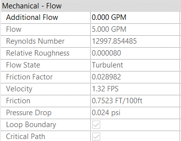
- Select the inline pump for the separated loop and review the values for pressure drop and flow.
Any changes made to this loop that would alter flow rates or pressure drop will now be seen at the inline pump.
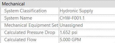
- From the Options Bar, change the Diameter of the flow and return pipes for the separated loop to 1".
- Review the calculated values for flow and pressure drop at the inline pump.
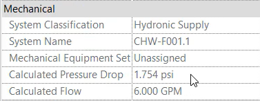
- In Properties, change the Chilled Water Flow rate at the fan coil unit to 6 GPM.
- Select the inline pump, and review the calculated values for flow and pressure drop.
- Select the fan coil unit for the separated loop.
- Click System Inspector.
- Select either of the two new systems that have been created due to hydraulic separation of this loop.
- Click OK.
- In the System Inspector, click Inspect to verify the direction of flow and to establish values at any section of pipe in the system.
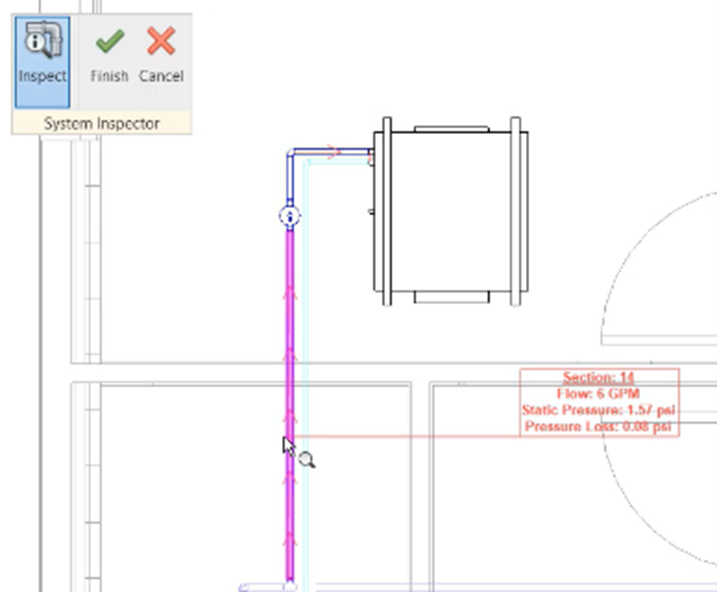
- Click Finish.
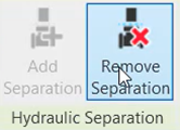
If separation of a loop is no longer required:
- Select the two original pipes used to create the separation.
- From the ribbon, click Remove Separation.
- Save the project.