Testing new duct and pipe types
Set properties and routing preferences, then test the new duct and pipe types.
Step-by-step guide
Set properties and routing preferences, then test the new duct and pipe types.
- Start a new project using the template Mechanical – Default.rte.
To create a new duct type:
- In the Project Browser, right-click the existing Standard pipe type and select Duplicate.
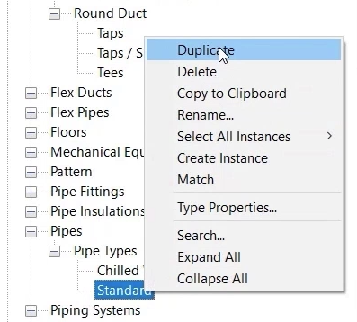
- Rename it to “Low Temperature Hot Water”.
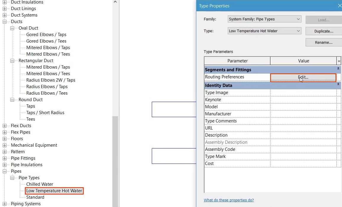
- Right-click the new pipe type and select Type Properties.
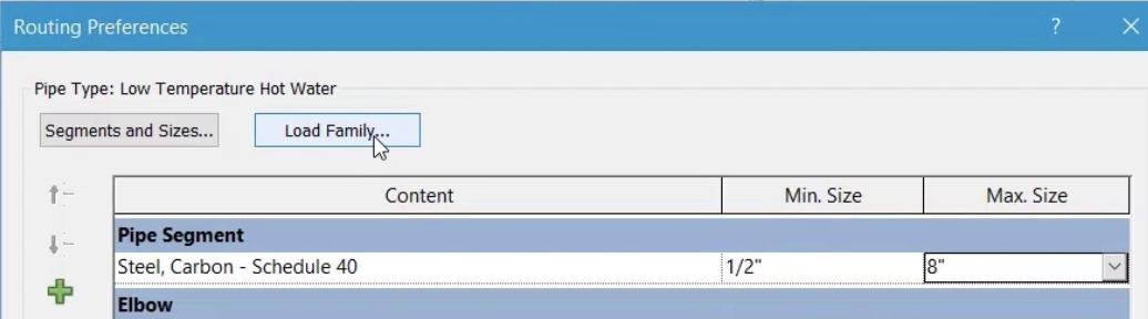
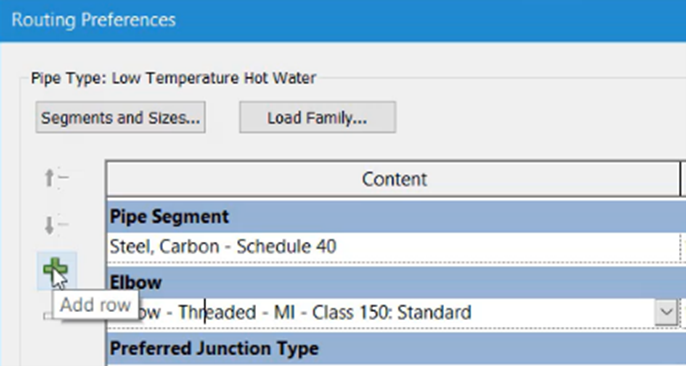
- In the Routing Preferences dialog box, click Edit.
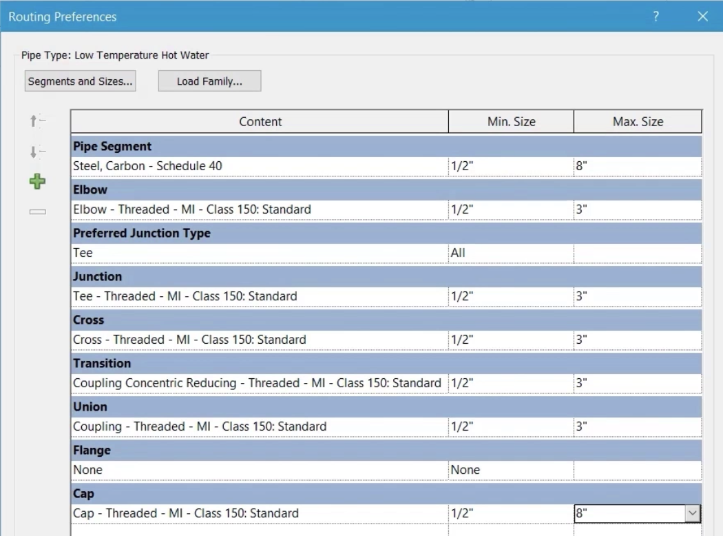
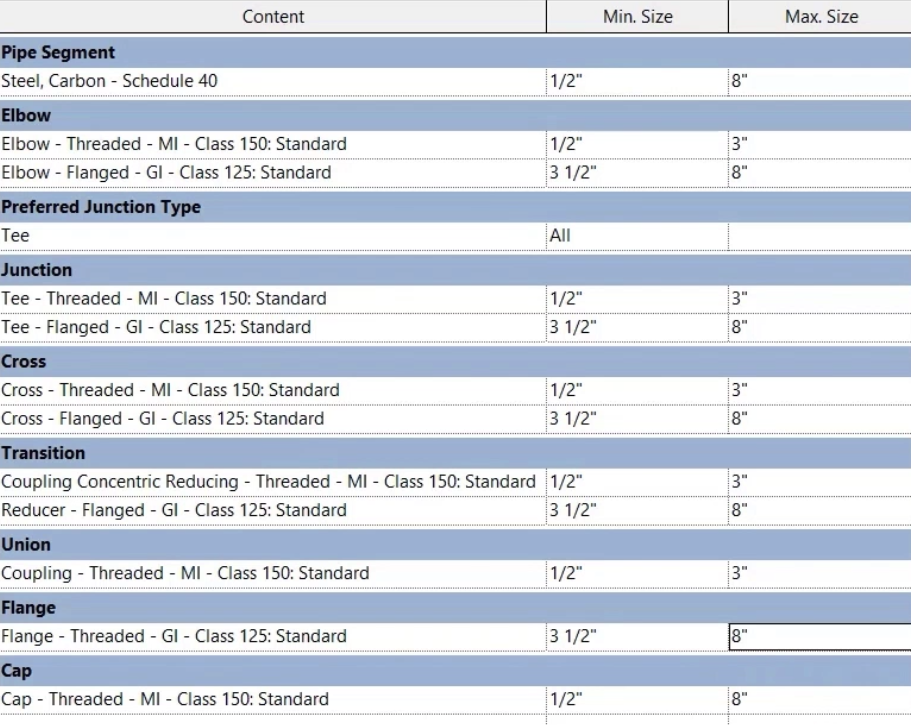
- Set the Pipe Segment to Carbon Steel Schedule 40.
- Set the Minimum Size to 1/2".
- Set the Maximum Size to 8".
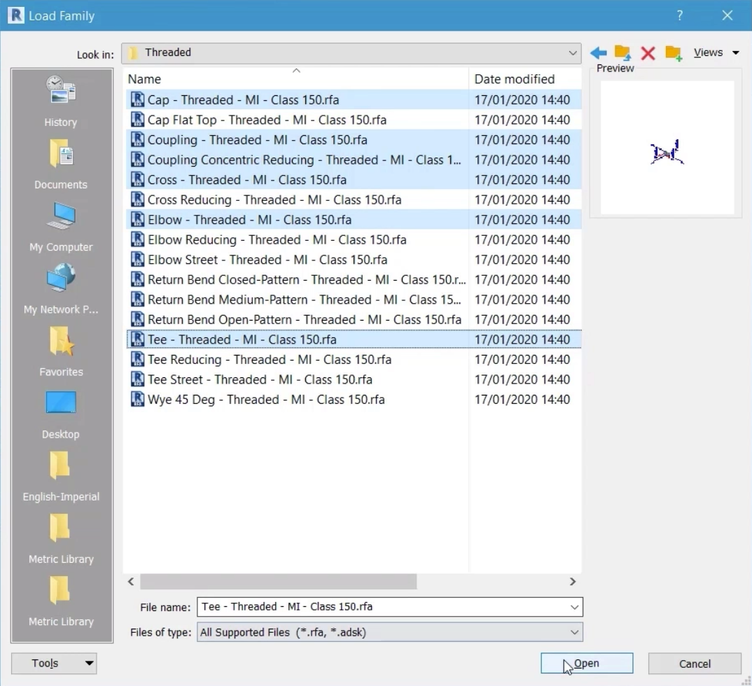
- Click Load Family to load the fittings to be used for the new standard.
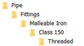
- In the Load Family dialog box, navigate to Pipe > Fittings > Malleable Iron > Class 150 > Threaded.
- From the available selection of fittings, choose Cap, Coupling, Coupling Concentric Reducing, Cross, Elbow, and Tee.
- Click Open.
- Change each fitting type to the malleable fittings just loaded.
- Set the Minimum Size for each fitting to 1/2" and the Maximum Size to 3".
- Set the Maximum Size for the end cap to 8".
For pipes sizes larger than 3", a flanged connection will be used.
- Click Load Family again.
- Navigate to Pipe > Fittings > Gray Iron Flanges > Class 125.
- Select the threaded flange.
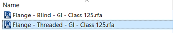
- Click Open.
- In the Routing Preferences dialog box, click Load Family again.
- Navigate to Pipe > Fittings > Gray Iron > Class 125 > Flanged.
- Select Cross, Elbow, Reducer, and Tee.
- Click Open.
- Select the row containing the threaded malleable iron elbow.
- Click Add row to add a second row for elbow fittings.
- Repeat this step to add additional rows for Junction, Cross, and Transition.
- For each of the new rows and the Flange row, assign the appropriate Gray Iron pipe fitting.
- Set the Minimum Size for each of the new fittings to 3-1/2" and the Maximum Size to 8".
- Click OK to close all dialog boxes.
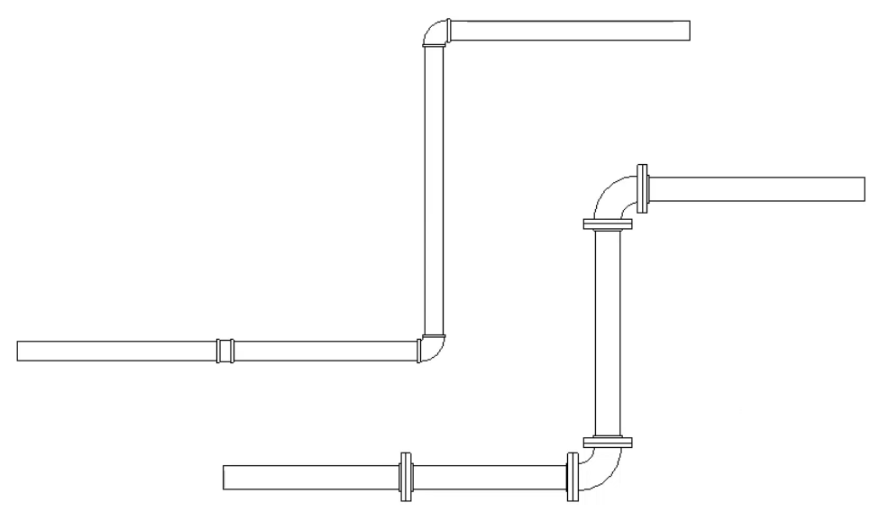
- Use the new pipe type to draw a run of pipe at 3" or less.
- Draw a similar section at 3-1/2" or above.
- From the Modify tab of the ribbon, use the Split Element tool to add a break in each pipe run.
- Review the range of fittings used within the same pipe type created at different sizes.