Conceptual to detailed mechanical layouts
Convert duct and pipe placeholder layouts.
Tutorial resources
These downloadable resources will be used to complete this tutorial:
Step-by-step guide
Convert duct and pipe placeholder layouts.
- Open the project M02_02.rvt.
- Ensure that the current view is HVAC > Floor Plans > 1 – Mech.
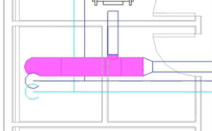
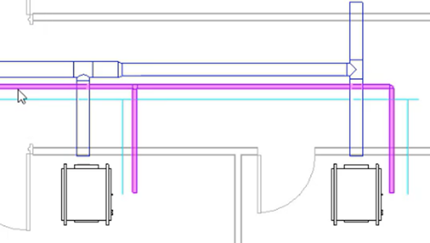
- Use TAB to chain-select the supply air duct network.
- In the Properties palette, Type Selector, change the duct type to Round Duct Tees.
- Set the Diameter to 8".
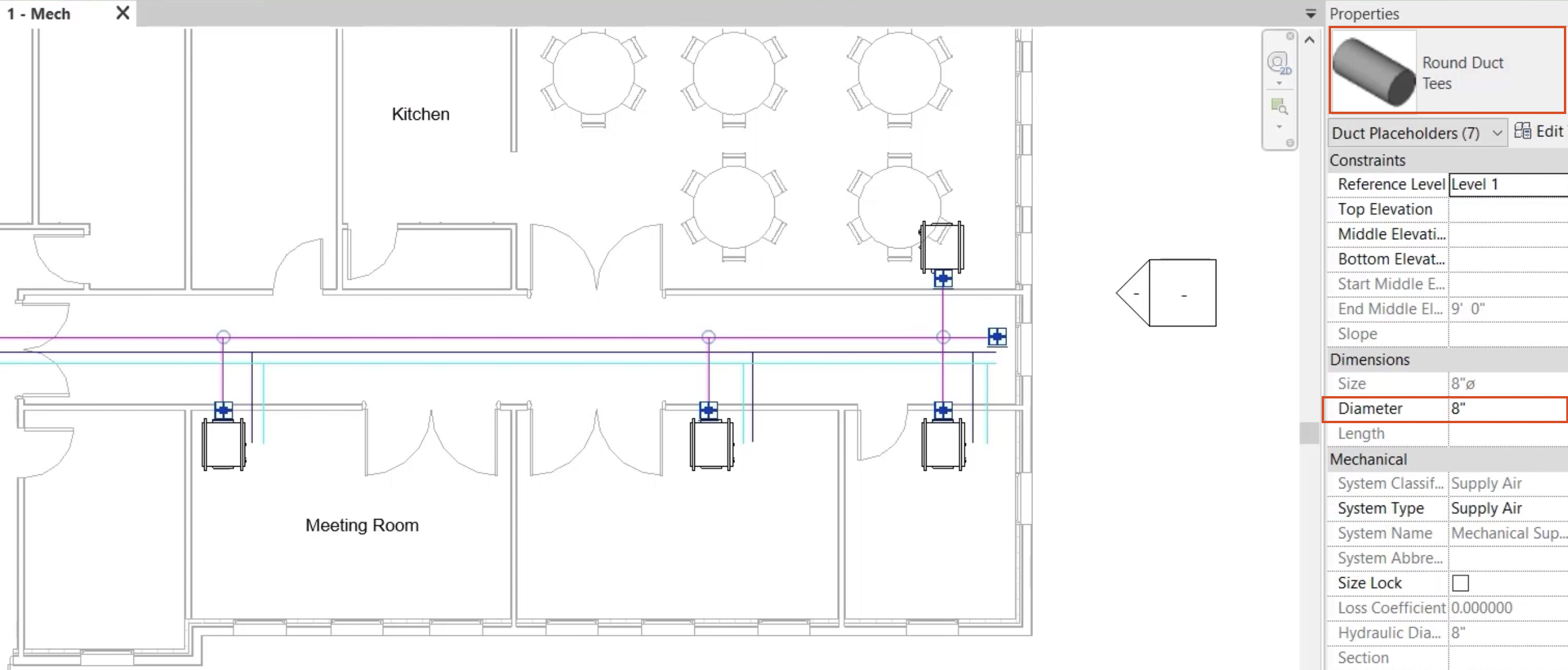
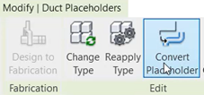
- With the network still selected, from the contextual ribbon tab, select Convert Placeholder.
Use the regular editing tools to make the necessary adjustments:
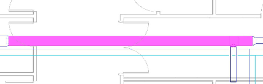
- Remove the excess duct from the right end.
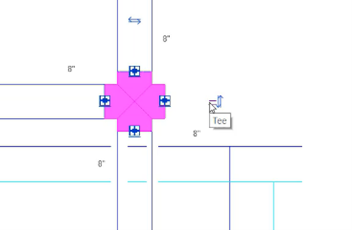
- Convert the cross fitting to a tee.
- From the ribbon, Modify tab, click the Split Element tool.
- Click to create a split in the duct just after each take-off along the main run, creating three splits in total.
- Select the duct at the riser end, including the section past the first branch, and set the diameter to 14".
- Select the next section as shown, including the section past the second branch, and set the diameter to 12".
- Select the next section as shown, including the section past the third branch, and set the diameter to 10".
- Select any section of duct and set the elevation for the entire network to 9' 4".
- Use TAB to chain-select the chilled water flow (supply) piping network and ensure that the Type Selector is set to Carbon Steel Screwed/Flanged Coupling.
- With the network still selected, on the contextual ribbon tab, click Convert Placeholder.
Again, use the regular editing tools to make adjustments:
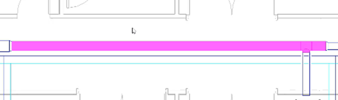
- Remove the excess pipe from the right end.
- Convert the tee fitting to an elbow.
- Select any section of pipe and set the elevation for the entire network to 8' 10".
- Use TAB to chain-select the chilled water flow (supply) piping network and set the diameter to 1-1/4".
- Follow the same procedure to convert the chiller water return piping network, using the same pipe type, and setting the elevation to 9' 9".
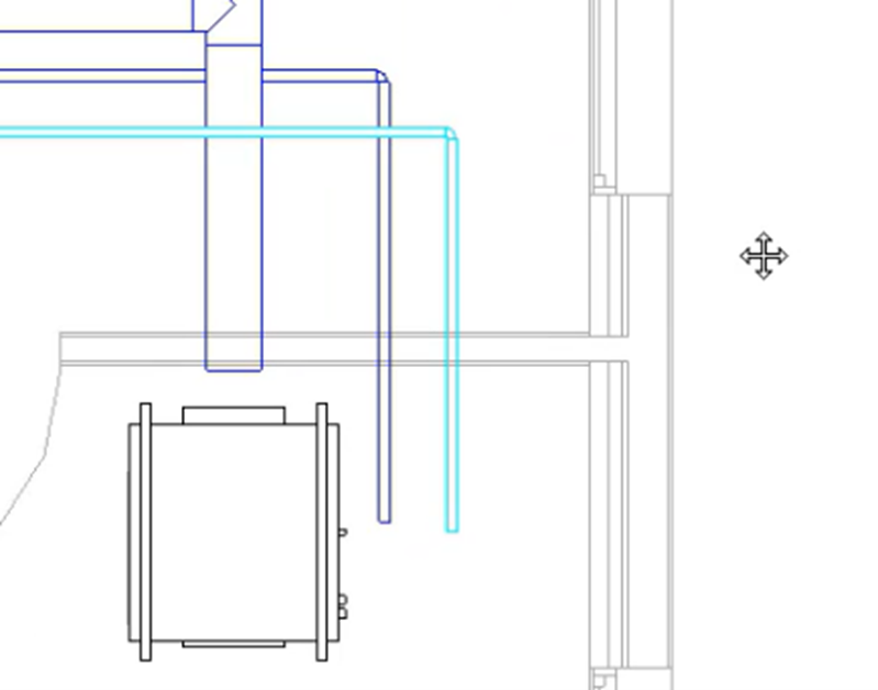
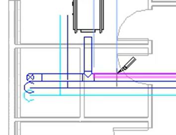
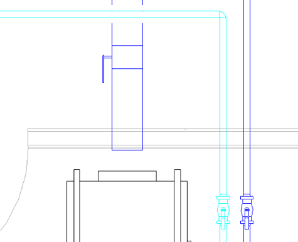
- Reposition the chilled water flow (supply) and return pipes as shown.
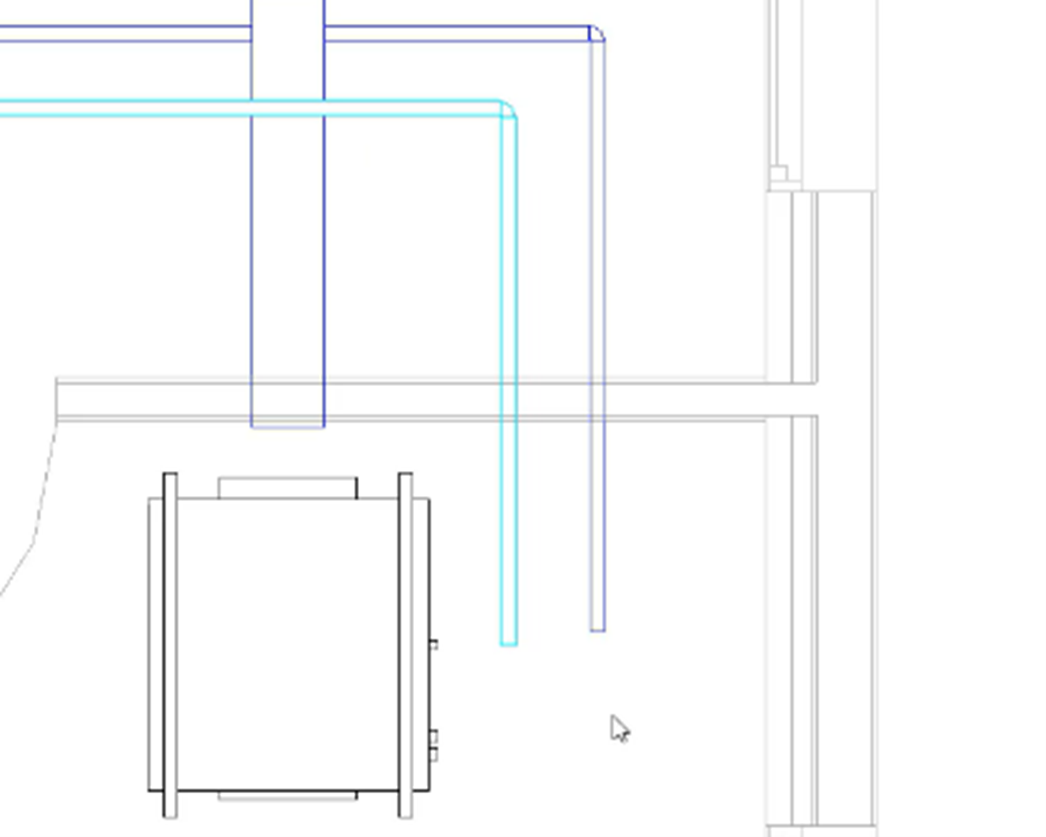
- Connect the chilled water flow (supply) and return pipes to the fan coil unit.
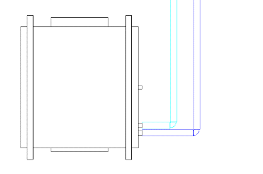
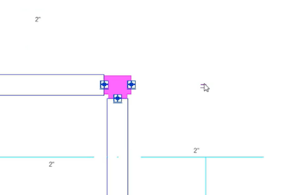
- From the ribbon, Systems tab, Plumbing & Piping panel, click Pipe Accessory.
- Use the Type Selector to add 2" ball valves as shown.
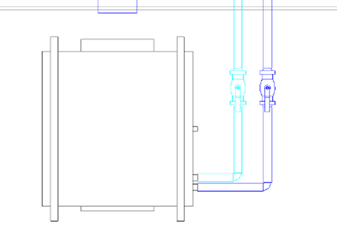
- Complete the detailed layout by adding pipe and duct accessories as required.
- Save the project.