• Revit

Review and create new view filters

Create new view filters.


Tutorial resources

These downloadable resources will be used to complete this tutorial:


00:03

View filters are one of the most effective ways to

00:06

control the appearance and visibility of mechanical systems within your

00:10

project.

00:12

In the following example,

00:13

we will create a range of view filters that

00:16

will identify various characteristics in duct and piping networks.

00:20

Then use that information to control the appearance

00:23

and visibility of associated elements within the project.

00:27

At the same time,

00:28

considering the options for the most

00:30

appropriate filter based on different requirements,

00:35

ensure the current view is set to H VAC floor plans. One

00:40

Mac

00:42

using color to distinguish between the various pipe and duct networks found

00:47

in a project provides a big advantage when working in busy areas.

00:52

Controlling the visibility of those same

00:54

networks provides a greater advantage where

00:57

multiple networks may be the same service type and the same color.

01:02

Few filters can be created to control

01:04

both appearance and visibility at varying levels.

01:07

Depending on the information in a system.

01:11

At a high level. Each system will have a system classification.

01:15

For example, this section of pipe is hydraulic supply

01:21

and this one hydraulic return

01:25

to create a filter. At this level,

01:27

we work with all piping networks that belong to the same system classification.

01:33

Open the visibility graphics override dialog box by typing VG from your keyboard

01:40

and then select the filters tab,

01:44

select edit new.

01:46

And let's go ahead and create a new filter that

01:48

controls the visibility of pipework based on its system classification.

01:55

Select new from the filters area of the

01:57

dialog box and name the filter hydraulic supply.

02:08

From the list of categories.

02:10

Select all of the piping options except piping systems.

02:15

Then set the filter rules to system classification,

02:20

the conditional statement to equals

02:24

and from the drop down menu, select hydraulic supply,

02:29

then select OK to close the dialog box.

02:34

Next

02:35

add the new filter to the list of filters that will be available for this view.

02:44

Although the graphic overrides can be set in the system's type properties.

02:49

A change to line

02:51

pattern or transparency within a filter will take precedence

02:57

set the line color to magenta

03:01

and the pattern to a lining line.

03:08

The enable filter option will determine whether the filter is applied to

03:12

this view and left unchecked elements will retain their original appearance.

03:18

The visibility option will either hide or

03:20

show the elements associated with this filter

03:24

with both options checked select. OK.

03:27

And all piping of the hydraulic supply classification in this view,

03:32

regardless of the service is now controlled by the filter.

Video transcript

00:03

View filters are one of the most effective ways to

00:06

control the appearance and visibility of mechanical systems within your

00:10

project.

00:12

In the following example,

00:13

we will create a range of view filters that

00:16

will identify various characteristics in duct and piping networks.

00:20

Then use that information to control the appearance

00:23

and visibility of associated elements within the project.

00:27

At the same time,

00:28

considering the options for the most

00:30

appropriate filter based on different requirements,

00:35

ensure the current view is set to H VAC floor plans. One

00:40

Mac

00:42

using color to distinguish between the various pipe and duct networks found

00:47

in a project provides a big advantage when working in busy areas.

00:52

Controlling the visibility of those same

00:54

networks provides a greater advantage where

00:57

multiple networks may be the same service type and the same color.

01:02

Few filters can be created to control

01:04

both appearance and visibility at varying levels.

01:07

Depending on the information in a system.

01:11

At a high level. Each system will have a system classification.

01:15

For example, this section of pipe is hydraulic supply

01:21

and this one hydraulic return

01:25

to create a filter. At this level,

01:27

we work with all piping networks that belong to the same system classification.

01:33

Open the visibility graphics override dialog box by typing VG from your keyboard

01:40

and then select the filters tab,

01:44

select edit new.

01:46

And let's go ahead and create a new filter that

01:48

controls the visibility of pipework based on its system classification.

01:55

Select new from the filters area of the

01:57

dialog box and name the filter hydraulic supply.

02:08

From the list of categories.

02:10

Select all of the piping options except piping systems.

02:15

Then set the filter rules to system classification,

02:20

the conditional statement to equals

02:24

and from the drop down menu, select hydraulic supply,

02:29

then select OK to close the dialog box.

02:34

Next

02:35

add the new filter to the list of filters that will be available for this view.

02:44

Although the graphic overrides can be set in the system's type properties.

02:49

A change to line

02:51

pattern or transparency within a filter will take precedence

02:57

set the line color to magenta

03:01

and the pattern to a lining line.

03:08

The enable filter option will determine whether the filter is applied to

03:12

this view and left unchecked elements will retain their original appearance.

03:18

The visibility option will either hide or

03:20

show the elements associated with this filter

03:24

with both options checked select. OK.

03:27

And all piping of the hydraulic supply classification in this view,

03:32

regardless of the service is now controlled by the filter.

Step-by-step guide

Create new view filters.

  1. Open the project M05_04.rvt.
  2. Ensure that the current view is HVAC > Floor Plans > 1 – Mech.
  • The Revit interface, with the project for this example open to the HVAC floor plan view.
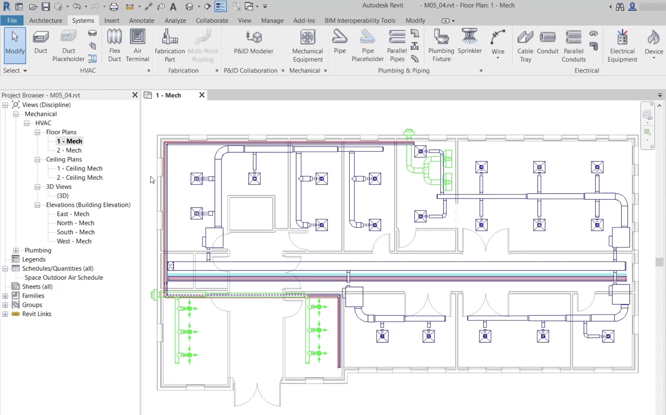
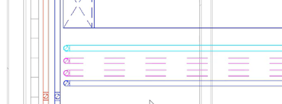
  1. Zoom into the area to the left end of the corridor.
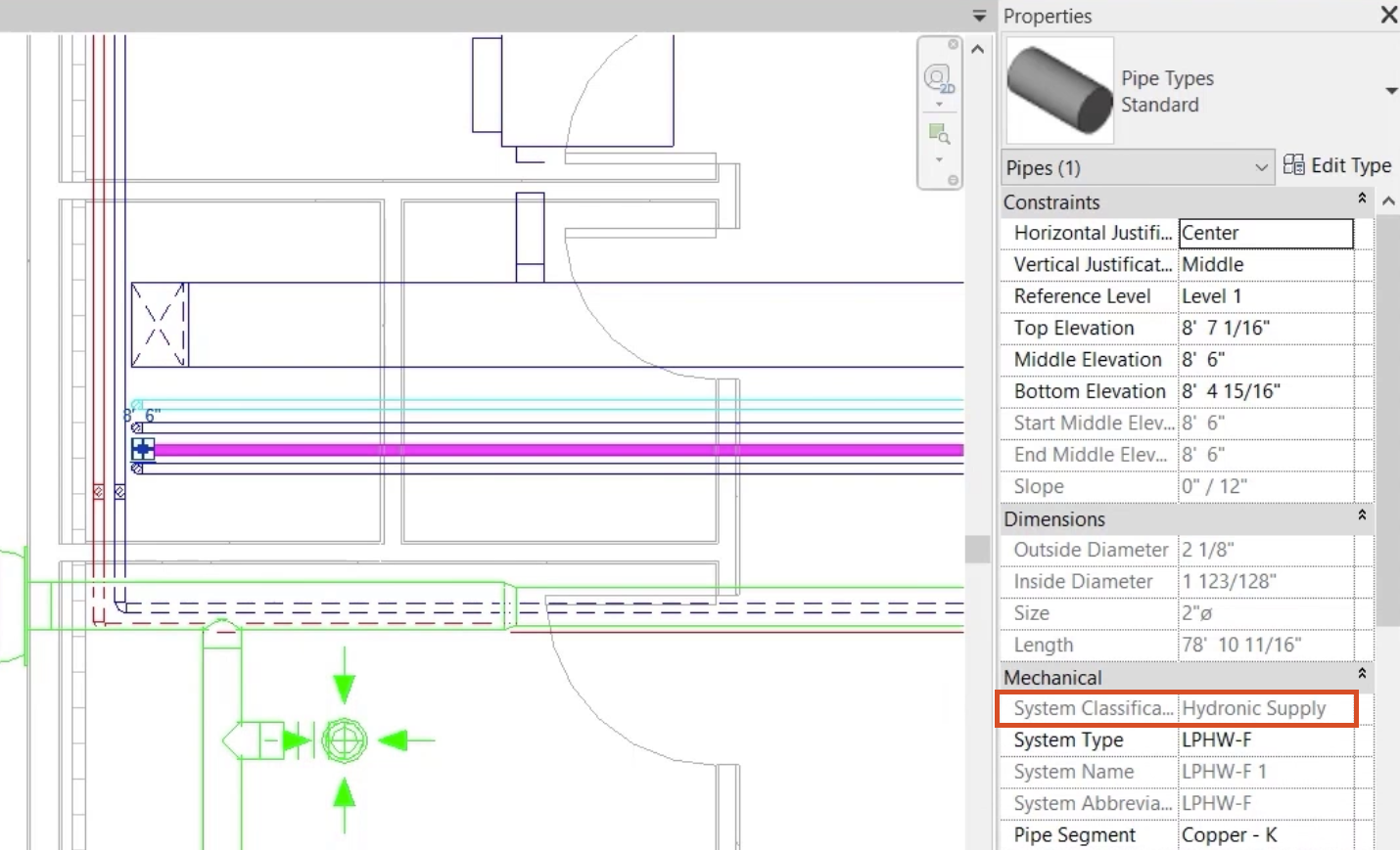
  2. Select various pipes to establish the System Classification of each.

System Classification is found in the Mechanical group of the Properties palette. In this case, all the flow and return pipes in the corridor are either Hydronic Supply or Hydronic Return.

  • In a zoomed-in view of the floor plan, a pipe is selected, and in Properties to the right, the System Classification of Hydronic Supply is highlighted in red.
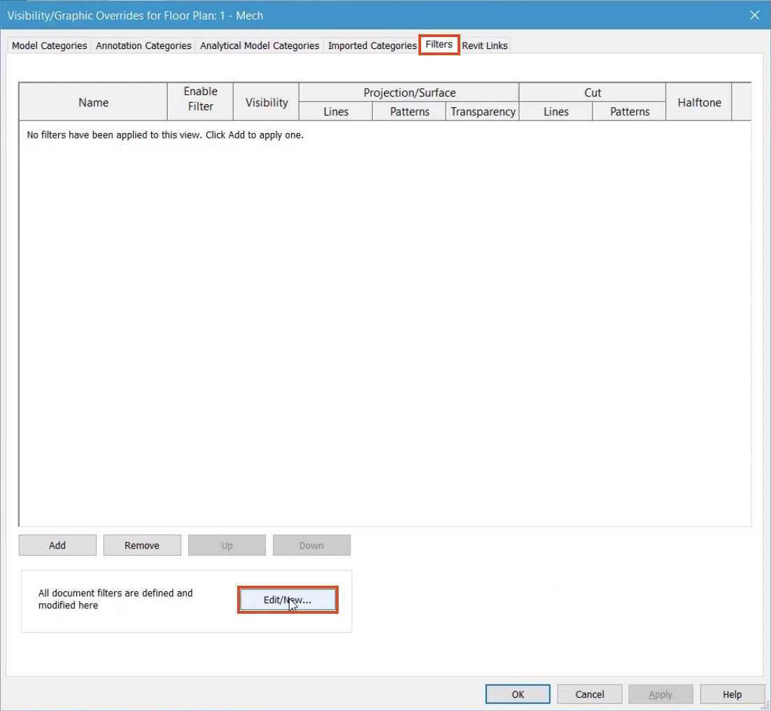
  1. Type "VG" to open the Visibility Graphics Override dialog box for this view.
  2. Switch to the Filters tab.
  3. Click Edit/New.
  • In the Visibility Graphics Override dialog box, on the Filters tab, the Edit/New button is selected and highlighted in red.
  1. To create a new filter, click New.
  2. Name the new filter "Hydronic Supply".
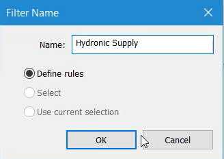
  • In the Filter Name dialog box, the name “Hydronic Supply” is entered for the new filter.
  1. Click OK.
  2. From the list of Categories, select all the options for Pipe, except Piping Systems.
  3. Set the Filter Rules to System Classification.
  4. Set the condition to equals.
  5. From the drop-down, select Hydronic Supply.
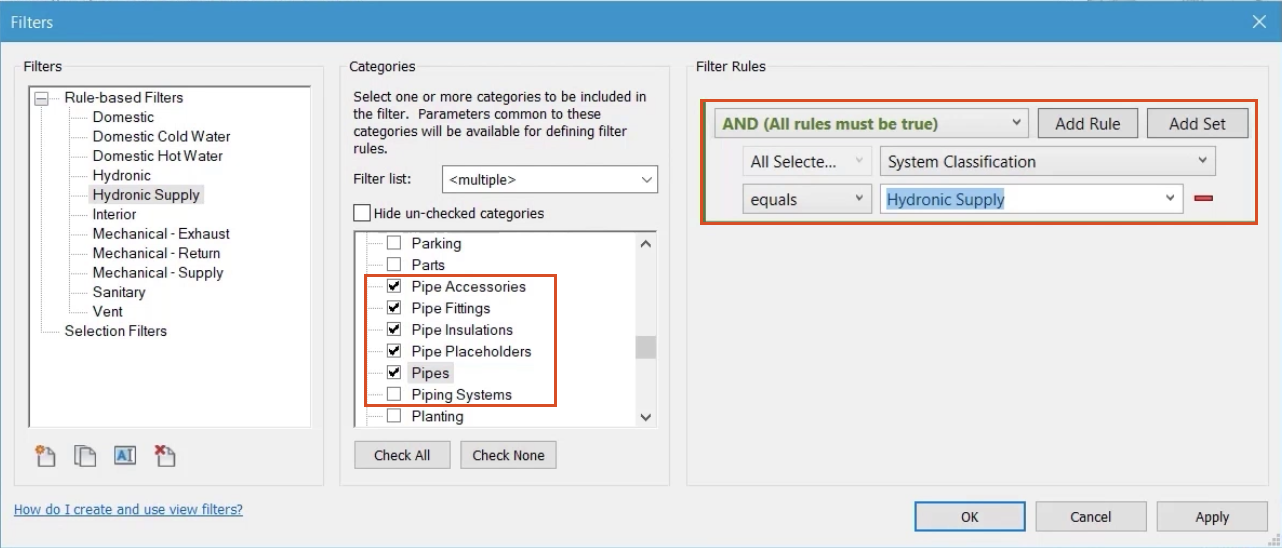
  • The Filters dialog box, with all options configured for this example and highlighted in red under the Categories and Filter Rules groups.
  1. Click OK.
  2. From the Visibility/Graphics dialog box, click Add.
  3. In the Add Filters popup, select the new Hydronic Supply filter.
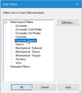
  • The Add Filters dialog box, with the new Hydronic Supply filter selected.
  1. Click OK.

To change the appearance of elements that will be included in this filter:

  1. In the Lines column, click Override.
  2. Set the Color to Magenta.
  3. Set the Pattern to Aligning Line.
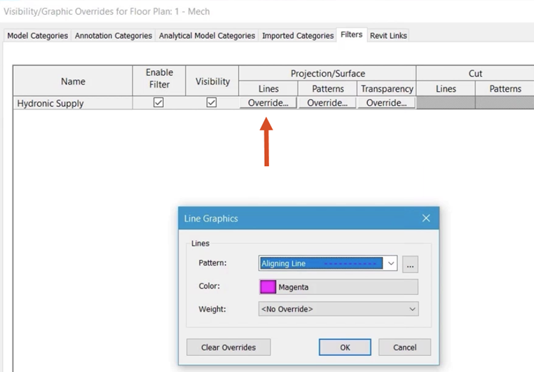
  • In the background is the Visibility/Graphics dialog box, Lines column, where Override is called out with a red arrow; and in the Line Graphics dialog box in front, the Pattern and Color have been selected for the new filter.
  1. Click OK.
  2. Verify that Enable Filter and Visibility are selected.
  3. Click OK to close the Visibility Graphics dialog box.

All piping that belongs to the System Classification of Hydronic Supply is now controlled by the filter, regardless of the service.

  • In a zoomed-in view of the floor plan, the Hydronic Supply pipes are shown in the line pattern and color that is defined by the new filter.
Was this information helpful?