Interrogate system information with the system browser
Review the system browser and use it to locate systems and elements.
Tutorial resources
These downloadable resources will be used to complete this tutorial:
Step-by-step guide
Review the System Browser and use it to locate systems and elements.
- Open the project M06_02.rvt.
- Ensure that the current view is HVAC > Floor Plans > 1 – Mech.
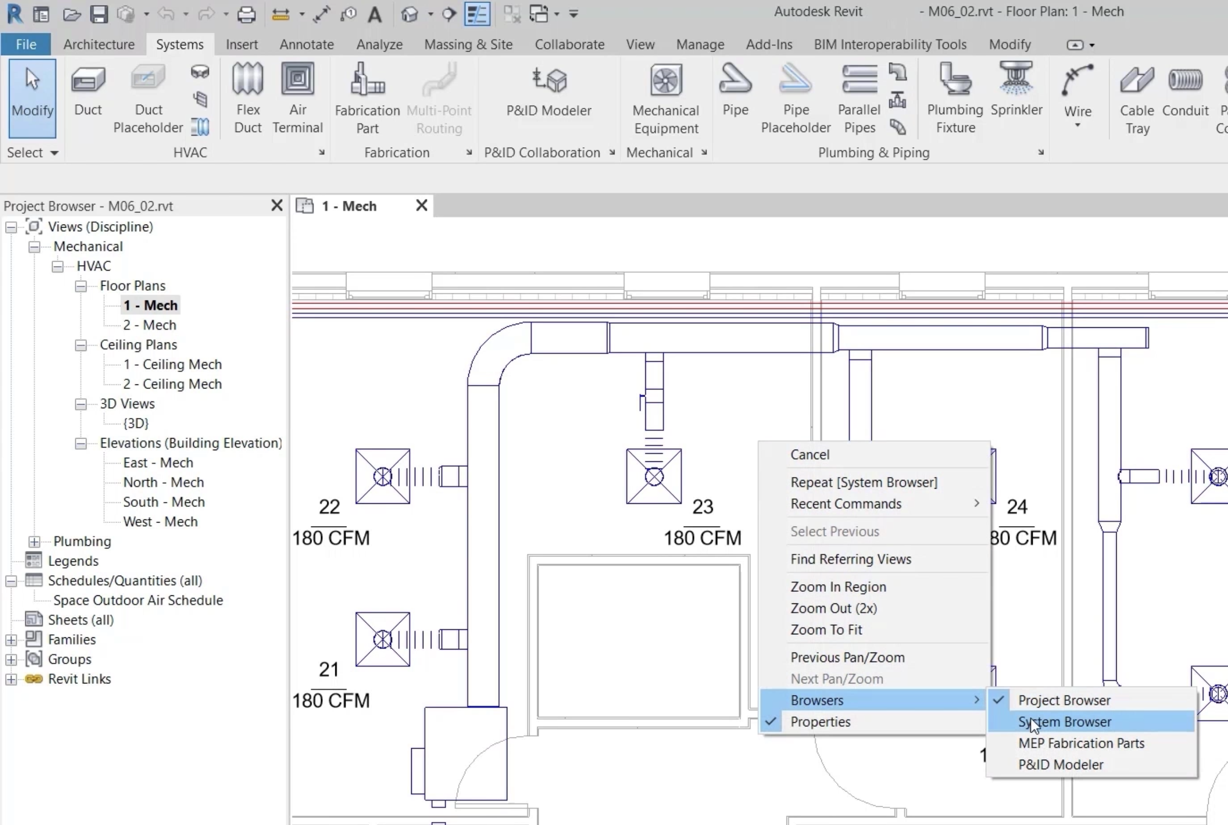
- To gain an overview of the systems in your project, right-click and select Browsers > System Browser.
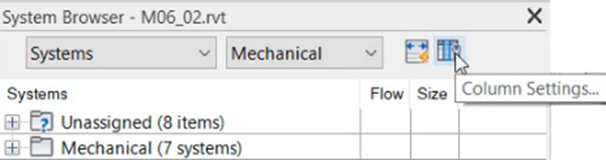
- In the System Browser, set the first drop-down to Systems.
- Set the second drop-down to Mechanical.
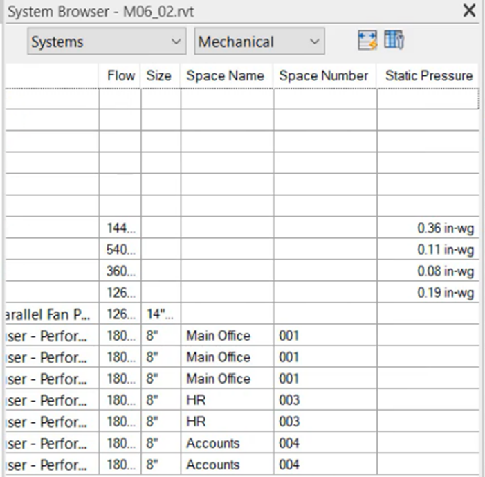
- Click Column Settings.
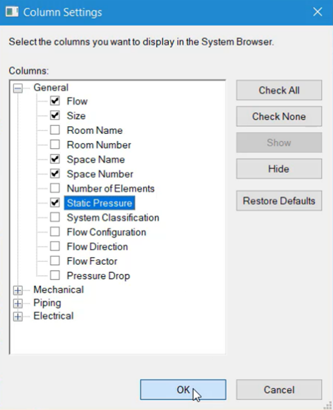
- Under General, select the Static Pressure column.
- Click OK.
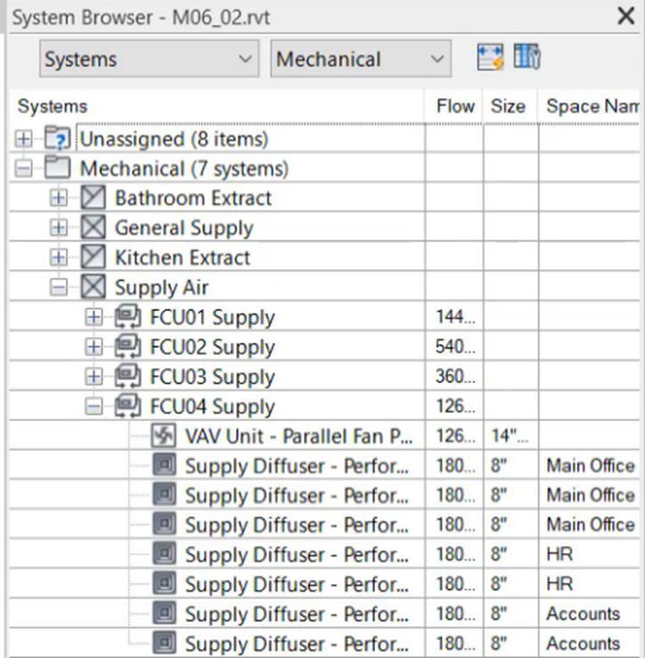
- In the System Browser, expand the Unassigned branch to review a list of elements that have yet to be connected to a system.
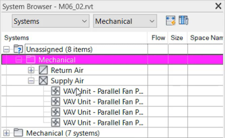
- In the System Browser, expand Mechanical > Supply Air > FCU04 Supply.
- Review the range of information for multiple elements and the system.
- Click and drag the horizontal scroll bar to view additional information.
- If required, widen the column headings to display all information available.
- From the System Browser, select system FCU04 Supply, and note that it appears highlighted in the plan view.
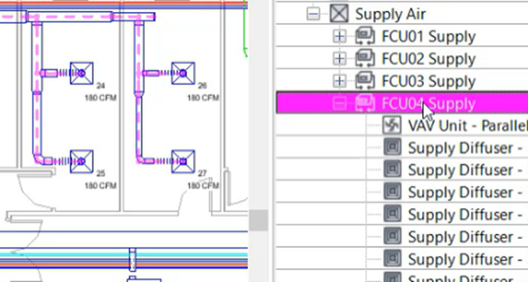
- Under FCU04 Supply, select the first air terminal to see that it is now highlighted in the plan view.
To highlight an element not currently visible in the floor plan:
- In the System Browser, select the element, such as an air terminal.
- Right-click the air terminal and select Show.
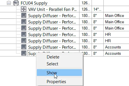
The view changes to show the specific element highlighted.
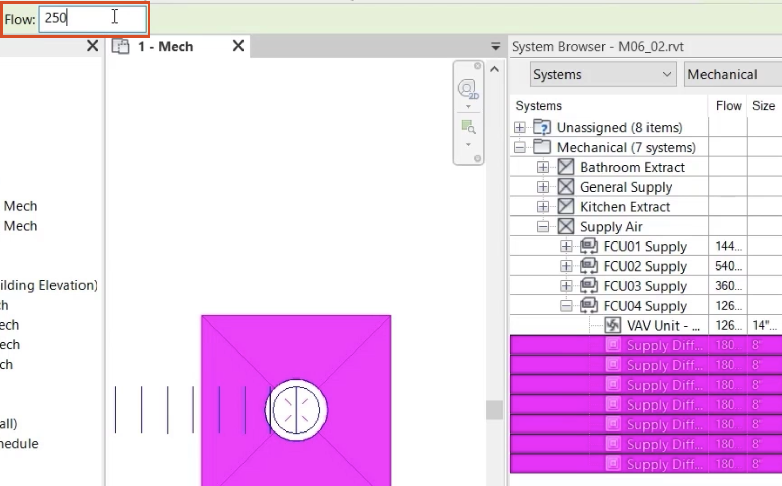
- In the System Browser, select all of the air terminals in the FCU04 Supply.
- From the Options Bar, change the Flow rate to 250 CFM.
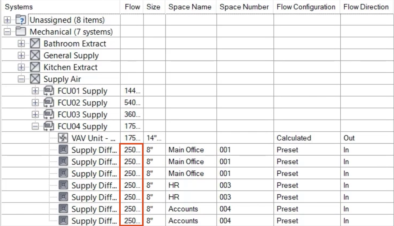
- A review of the System Browser shows the updated Flow rates for the air terminals.
- Save the project.