Applying new view filters
Apply view filters to control system appearance and visibility.
Tutorial resources
These downloadable resources will be used to complete this tutorial:
Step-by-step guide
Apply view filters to control system appearance and visibility.
- Open the project M05_04.rvt.
- Ensure that the current view is HVAC > Floor Plans > 1 – Mech.
- Select the main run of duct in the corridor.
- In the Properties palette, confirm that the System Abbreviation is GS (general supply).
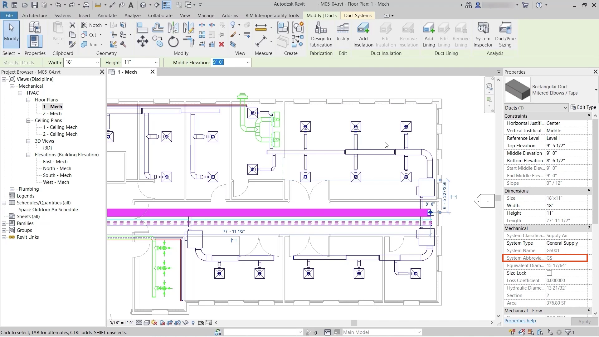
- Select any section of duct connected to a fan coil unit to confirm the System Abbreviation of FCU-S (fan coil unit supply).
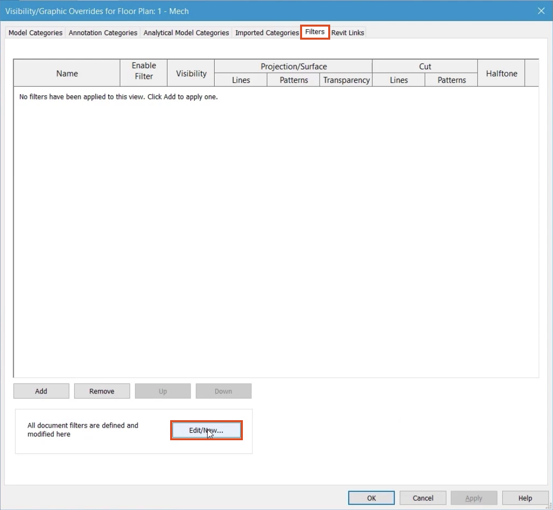
- Type "VG" to open the Visibility/Graphics dialog box for this view.
- Switch to the Filters tab.
- Click Edit/New.
- To create a new filter, click the New button.
- Name the filter "FCU Systems".
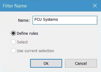
- Click OK.
- From the list of categories, select all options for duct, including Flex Duct and Air Terminals. Do not include Duct Systems.
- Set the Filter Rules to System Abbreviation.
- Set the condition to equals.
- From the drop-down, select FCU-S.
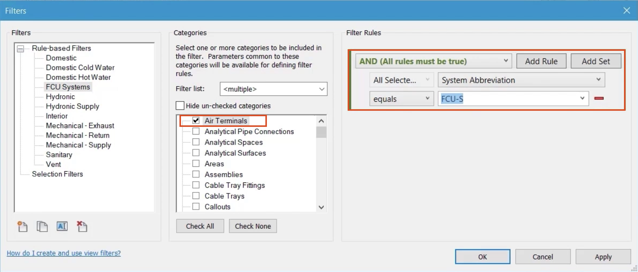
- Click OK.
- From the Visibility/Graphics dialog box, click Add.
- Select the new FCU Systems filter.
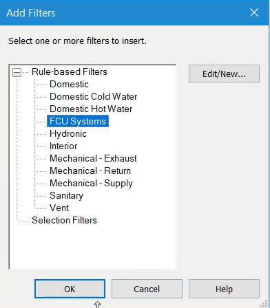
- Click OK.
- For the FCU Systems filter, deselect the Visibility option.
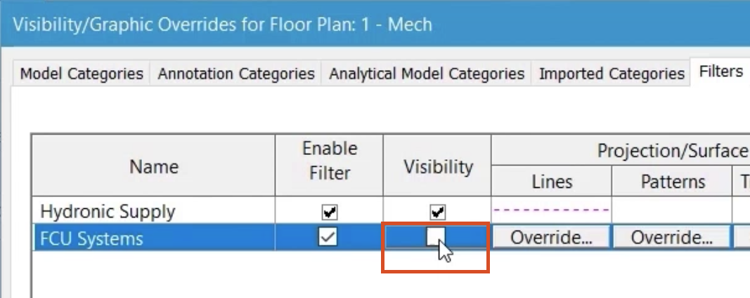
- Click OK to close the Visibility/Graphics dialog box.
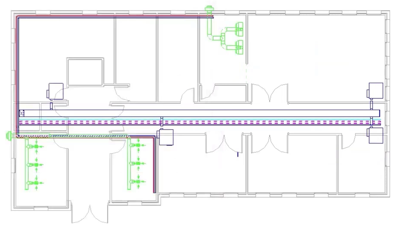
All systems with the abbreviation FCU-S are controlled by the filter and are no longer visible in this view.
A more granular method to using filters with systems in Revit is to use unique system names.
- Reopen the Visibility/Graphics dialog box.
- Click the Filters tab.
- For the FCU Systems filter, turn on the Visibility.
- Click Edit/New.
- Click Duplicate to create a copy of the FCU Systems filter.
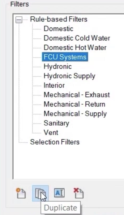
- Right-click Duplicate and select Rename.
- Enter a New name of "FCU01 Supply".
- Click OK.
- Set the Filter Rules to System Name.
- From the drop-down, select FCU01 Supply.
Note: All systems in the project have a unique name, so that more efficient filtering can be achieved.
- From the list of Categories, select Mechanical Equipment.
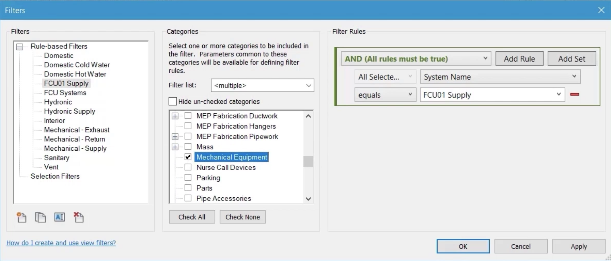
- Click OK.
- From the Visibility/Graphics dialog box, click Add.
- Select the new FCU01 Supply filter.
- Click OK.
- Deselect the Visibility option for the new filter.
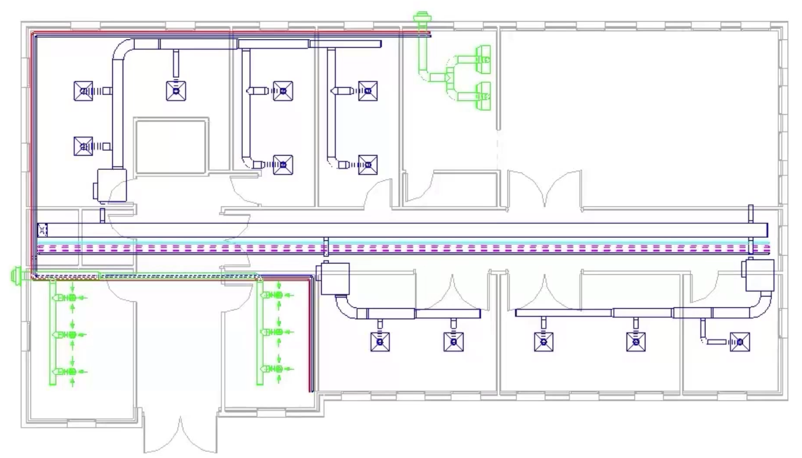
A review of the floor plan shows that only the system named in the filter has been affected and is no longer visible.
- Save the project.