Testing new ducting and piping systems
Set system properties and test new duct and piping systems.
Tutorial resources
These downloadable resources will be used to complete this tutorial:
Step-by-step guide
Set system properties and test new duct and piping systems.
- Open the project M01_03.rvt.
- Ensure that the current view is HVAC > Floor Plans > 1 – Mech.
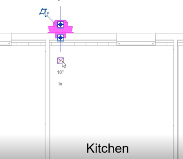
- In the kitchen, select the centrifugal fan.
- Click the Create Duct icon.
- Draw a section of duct extending away from the fan.
- Select one section of duct and review the mechanical properties, including the system type, name, and abbreviation.
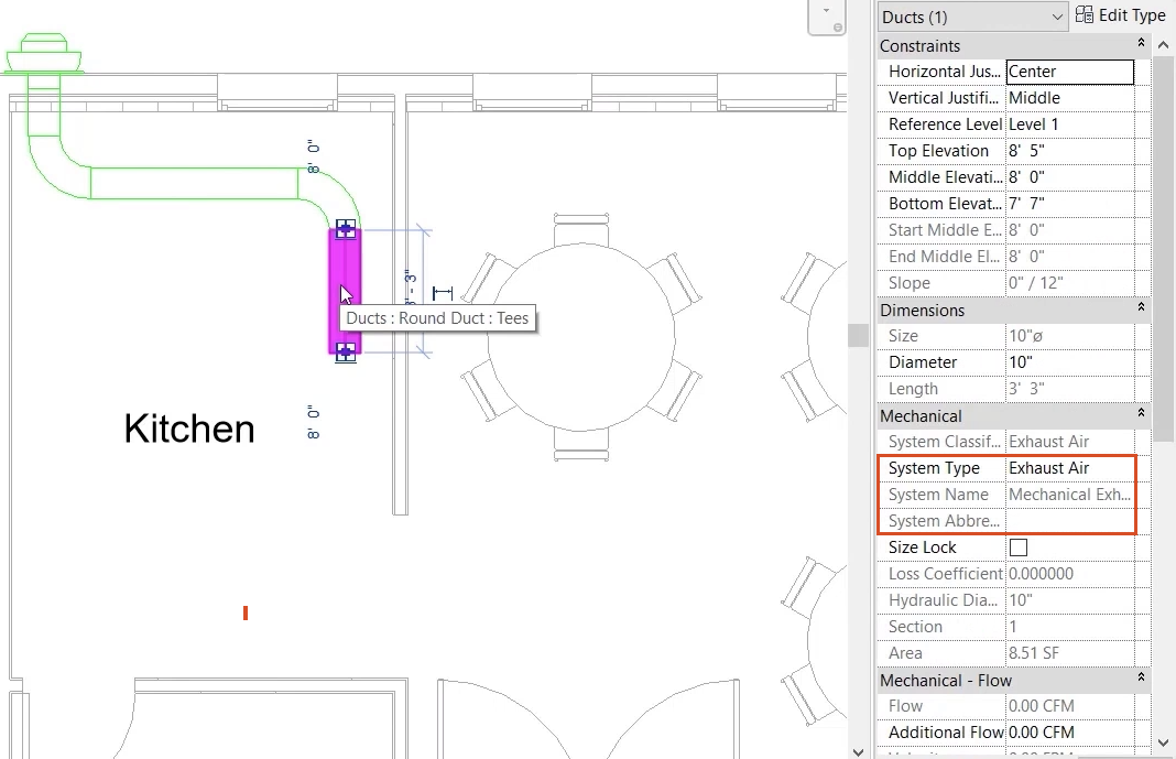
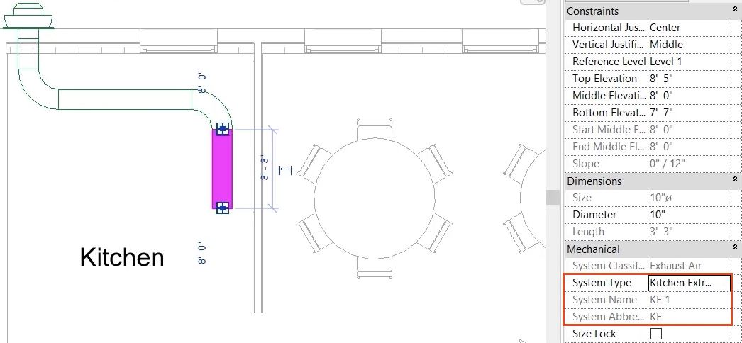
- Change the System Type to Kitchen Extract.
Note the update to the value for System Abbreviation to KE, and the default system name of KE 1. The system color also changes to match a color set previously in the Type Properties.
- In the Project Browser, right-click the Hydronic Supply piping system and select Duplicate.
- Rename it "CHW-F" for Chilled Water Flow. (Chilled Water Flow is often referred to as Chilled Water Supply.)
- Right-click the new CHW-F system and select Type Properties.
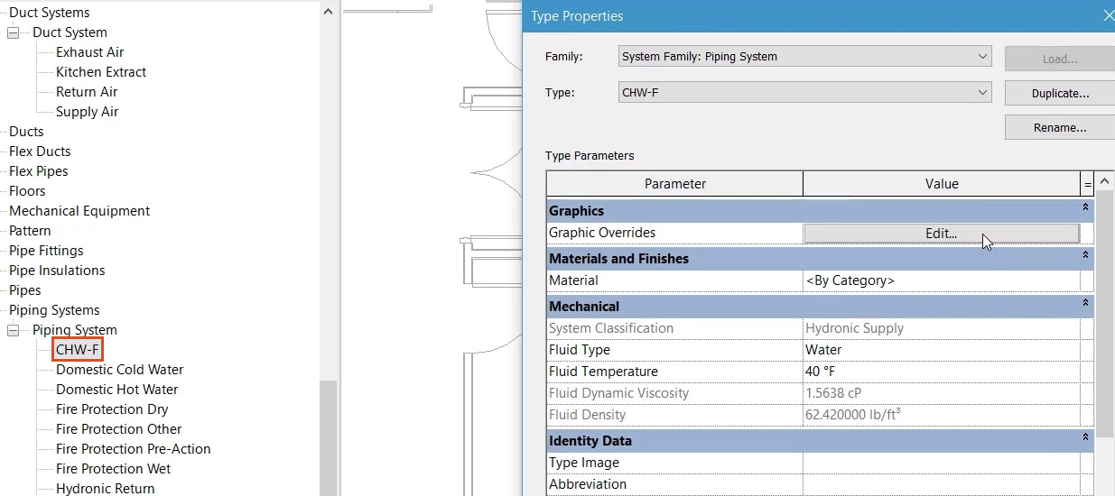
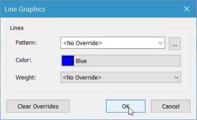
- In the Type Properties dialog box, next to Graphics Overrides, click Edit.
- In the Line Graphics dialog box, change the Color to blue.
- Click OK.
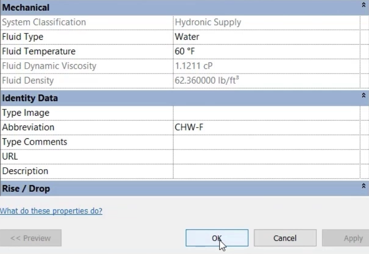
- Set the Fluid Type to Water.
- Set the Fluid Temperature to 60 degrees Fahrenheit.
- Set the system Abbreviation to CHW-F.
- Click OK to close the dialog box.
- In the Meeting Room, select the fan coil unit.
- Click Draw Pipe.
- At the IN connection, draw a short section of pipe.
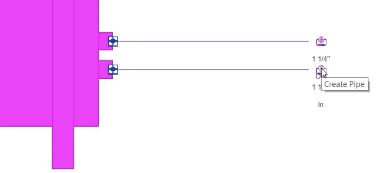
- Ensure that the pipe type is set to Carbon Steel Screwed/Flanged Coupling.
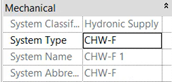
- Select one section of pipe and review the mechanical properties, including the System Type, System Name, and System Abbreviation.
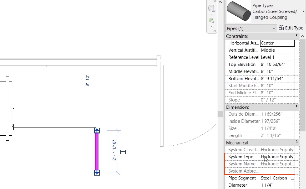
- Change the System Type to CHW-F.
Note the update of the System Abbreviation to CHW-F and the System Name to CHW-F 1. The color of the system also changes to match the choice made previously.
- Save the project.