Creating an integrated 1D model
Link river and urban drainage networks to create an integrated model.
Tutorial resources
These downloadable resources will be used to complete this tutorial:
Step-by-step guide
To create an integrated model, the river and urban drainage networks need to be linked. This can be done in 1D with conduits that spill from the urban drainage network into the river.
- Open the transportable database .icmt file for this tutorial.
- In the transportable database window, right-click the top-level folder and select Copy.
- In the Model Group window, right-click the Database and select Paste.
- From the Database, double-click 1D Integrated Model to open the river model on the GeoPlan.
- Expand the 1D Sewer Model group to display its contents.
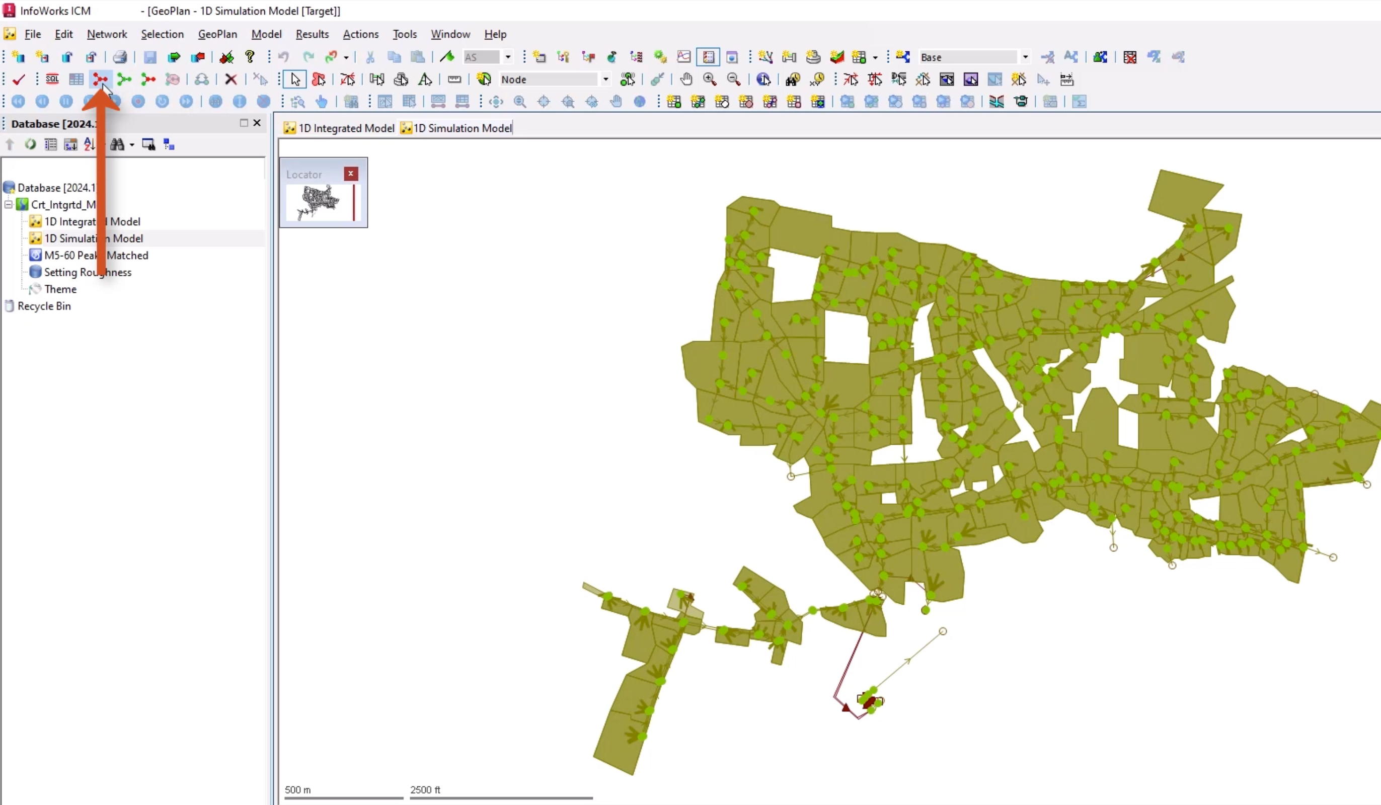
- Double-click 1D Simulation Model to open the sewer model on the GeoPlan.
- With the 1D Simulation Model window selected, from the Selection toolbar, click Select all objects.
- From the Edit menu, select Copy object(s).
- Switch to the 1D Integrated Model window.
- From the Edit menu, select Paste append object(s). This pastes the urban drainage network into the new network.
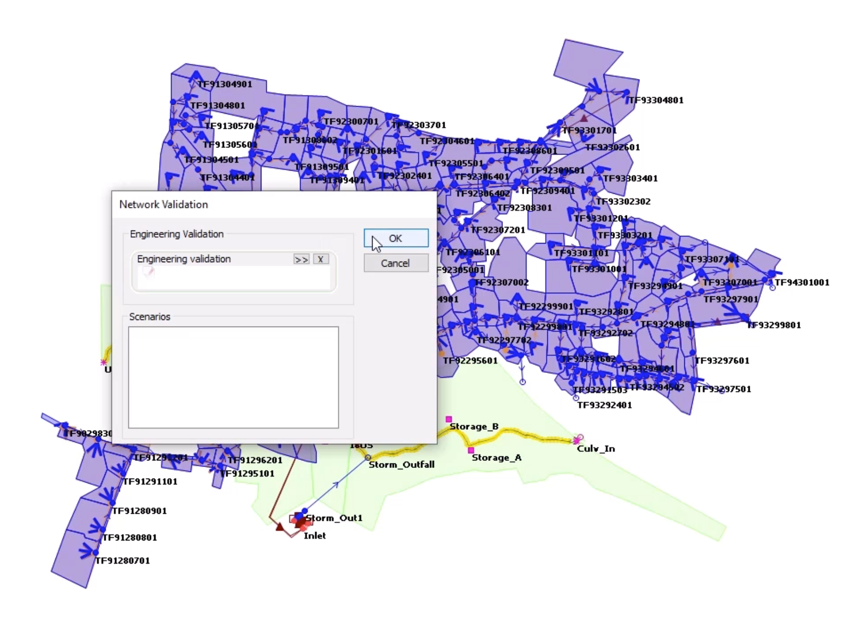
- Click Validate to make sure there are no errors in the network.
- Click OK.
- Click Commit changes to database to save changes.
- Add a comment, such as “Copied across sewer model”.
- Click OK.
At the moment, the river network and urban drainage network co-exist within the same model network. However, there is nothing linking the two components of the model.
To improve visibility, add labels and remove visual clutter:
- Right-click the GeoPlan and select Properties & Themes to open the Properties and Themes dialog box.
- On the Layers and Themes tab, in the Node row, enable AutoLabel.
- In the rows for Subcatchments and Storage areas, disable Display.
- Click OK.
To couple the 1D components together:
- From the GeoPlan Tools toolbar, click Find in GeoPlan.
- Perform a Quick Find for TF91299306.
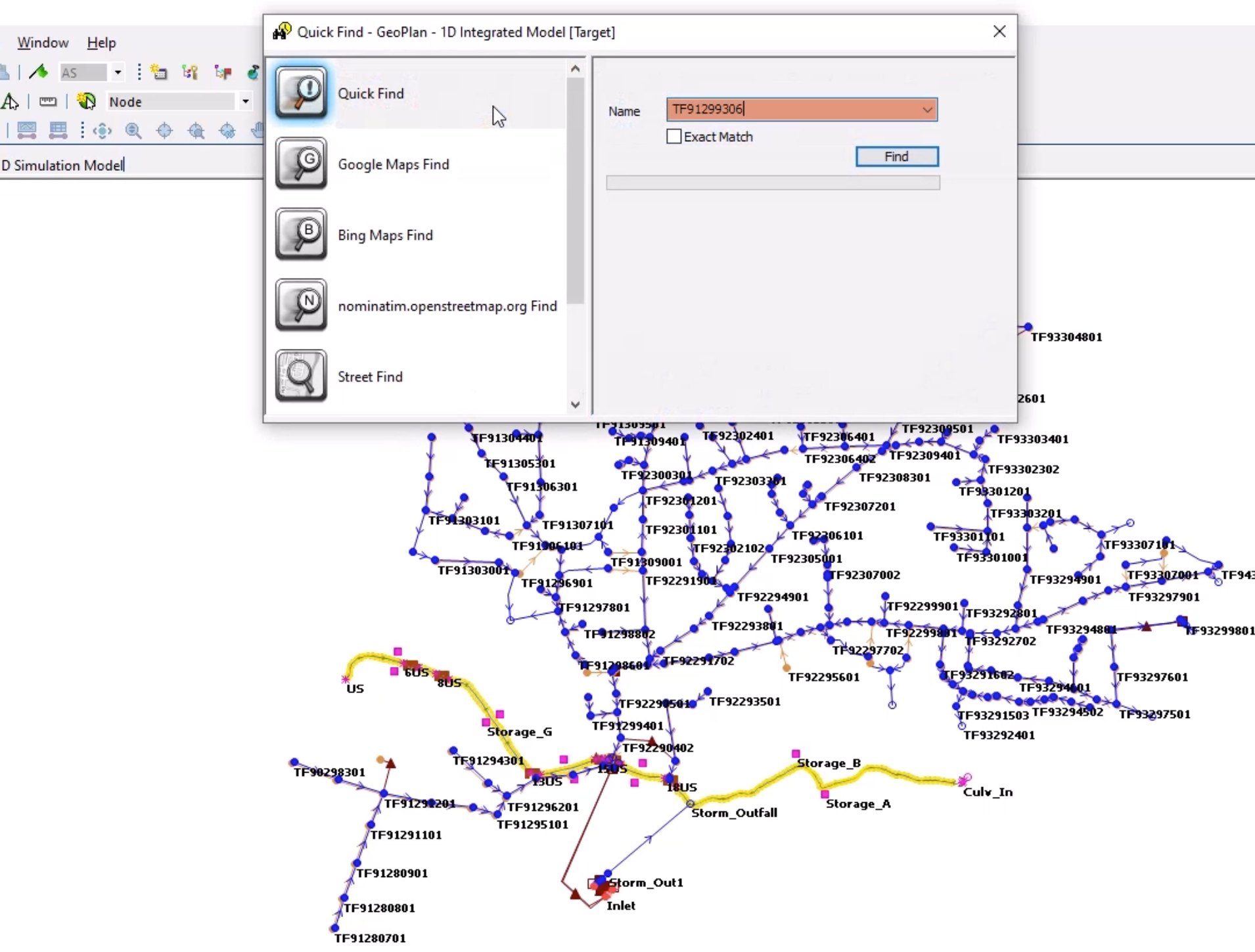
- Once the node is located, Close the Quick Find window.
There are three outfalls at this location. Currently, flow is lost from the system at these points rather than being transferred to the river network. The sewers can be connected to the river using the break nodes.
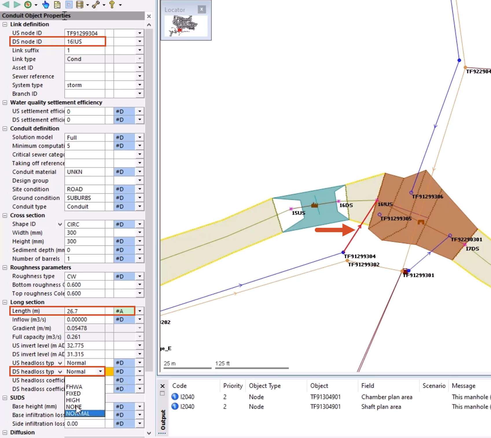
- Double-click conduit TF91299304.1, which discharges to outfall TF21299305.
Note: While the GeoPlan properties of the conduit locations can be changed, it is important to prevent ICM from adjusting the physical properties.
- In the Properties window, for the Length field, change the flag to #A. This prevents ICM from automatically updating the length.
- Optional: To add a user-defined flag, from the File menu, select Database management > User defined flags.
- In the Properties window, change the DS Node ID to 16!US.
This automatically moves the link. An inline validation warning appears for the DS headloss type field, as it is no longer appropriate and was developed for headloss at typical manholes.
- Change the DS headloss type value to NONE.
Using this same process, connect the following links:
- Connect link TF92290404.1, which discharges to outfall TF91299306, by changing the DS Node ID to 16!US.
- Connect link TF91299303.1, which discharges to outfall TF92290301, by changing the DS Node ID to 17DS.
- Connect link TF92291202.1, which discharges to outfall TF92291201, by changing the DS Node ID to 18US.
IMPORTANT: For the first two, remember to change the Length field flag and set the DS headloss type to NONE. The third link is a flap valve, so only the new DS node ID needs to be set.
Often, it is necessary to add new break nodes into the network so that the sewers can be connected to the river. It is best to plan for this during the original river build, but that is not always possible if models are inherited. When a break node is added to split the river reach, it creates an interpolated section. This is not always logical, and sometimes the geometry can become skewed. When this occurs, the river reaches should be manually corrected and rebuilt.
- Click Find in GeoPlan.
- Perform a Quick Find for Storm_Outfall.
- Once the node is located, Close the Quick Find window.
- On the GeoPlan, double-click Storm_Outfall to open the Properties window.
- Change the Node type to Break. Do not worry about the inline validation error that is created.
- On the GeoPlan, double-click the incoming link object Conduit: Storm_Out1.1 to open its Properties window.
- For the Length field, change the flag to the user-defined flag.
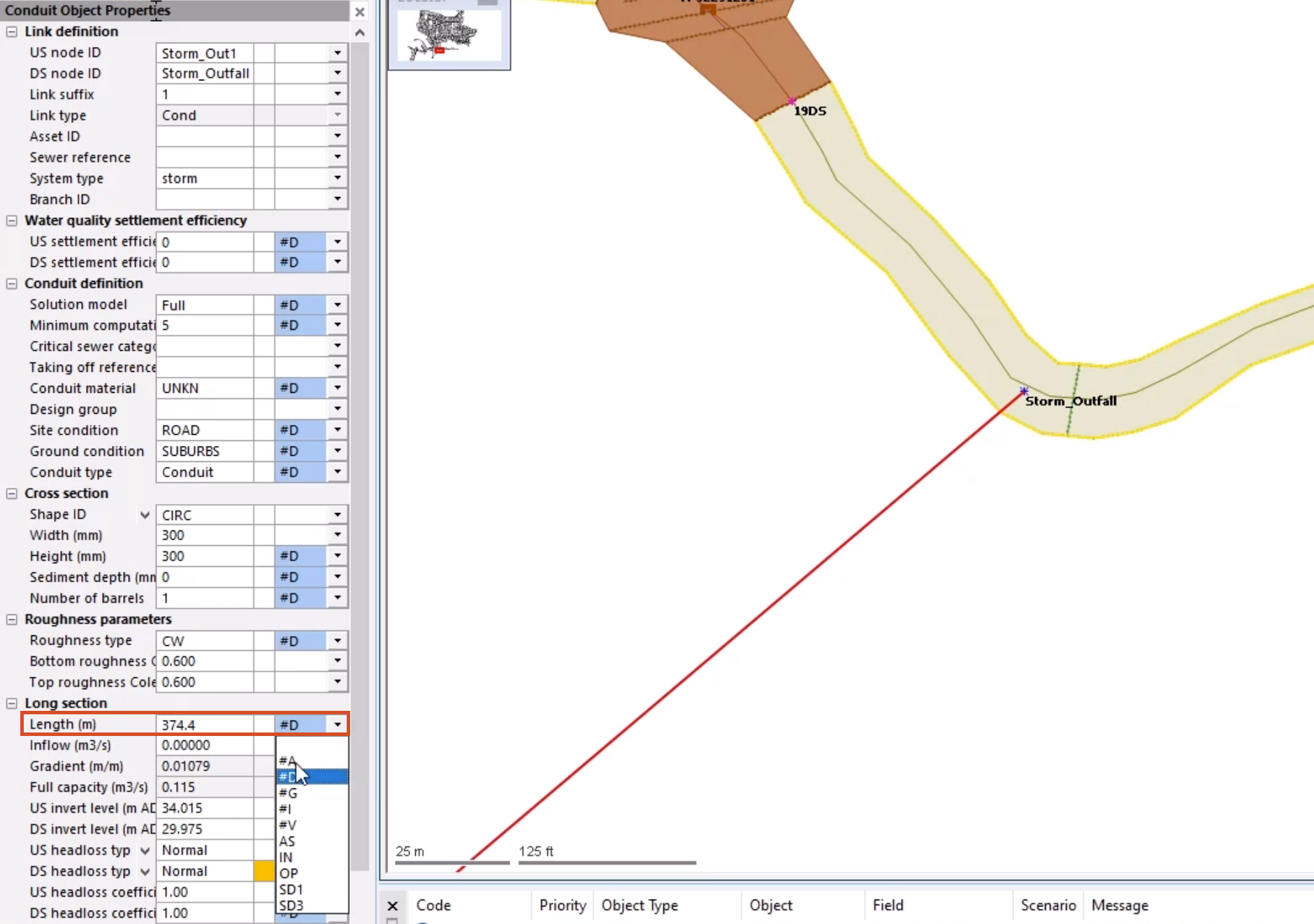
- Set the DS headloss type to NONE.
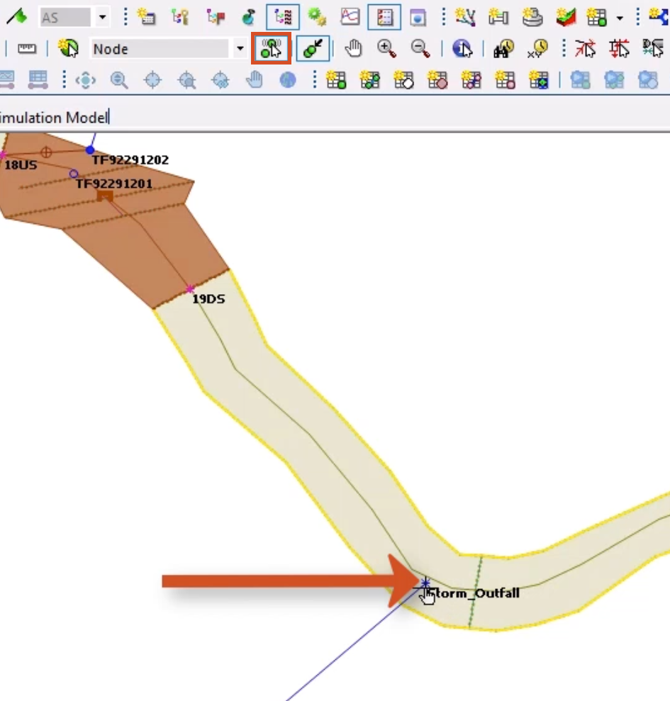
- From the GeoPlan Tools toolbar, select Edit object geometry.
- Select node Storm_Outfall. The node turns red to indicate that it is selected.
- Drag the node over the river center line, and drop it in a location that intersects the line.
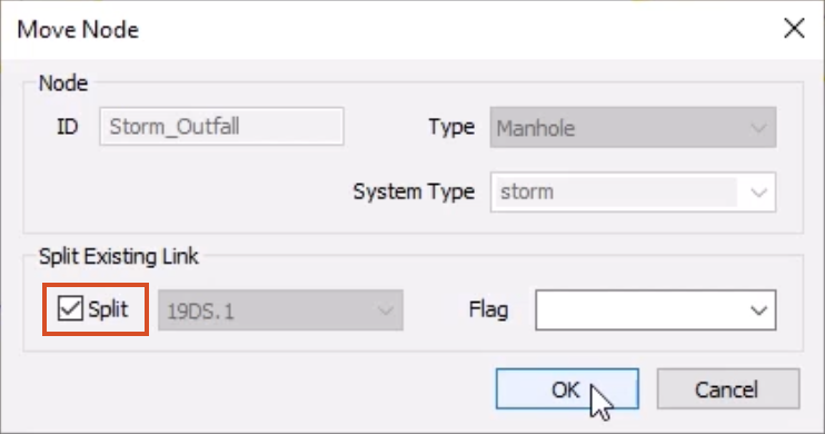
- In the Move Node popup, in the Split Existing Link section, enable Split.
- Click OK.
ICM generates a new interpolated cross section at the break node location, and the river reach is now split into two.
- Double-click the river reaches on either side of the new cross section to check the Properties for validation warnings.
The upstream river reach looks good, but the downstream reach displays several inline validation warnings.
To rebuild this river reach:
- Make sure that river reach Storm_Outfall.1 is selected.
- From the Model menu, select River reach > Build sections from lines.
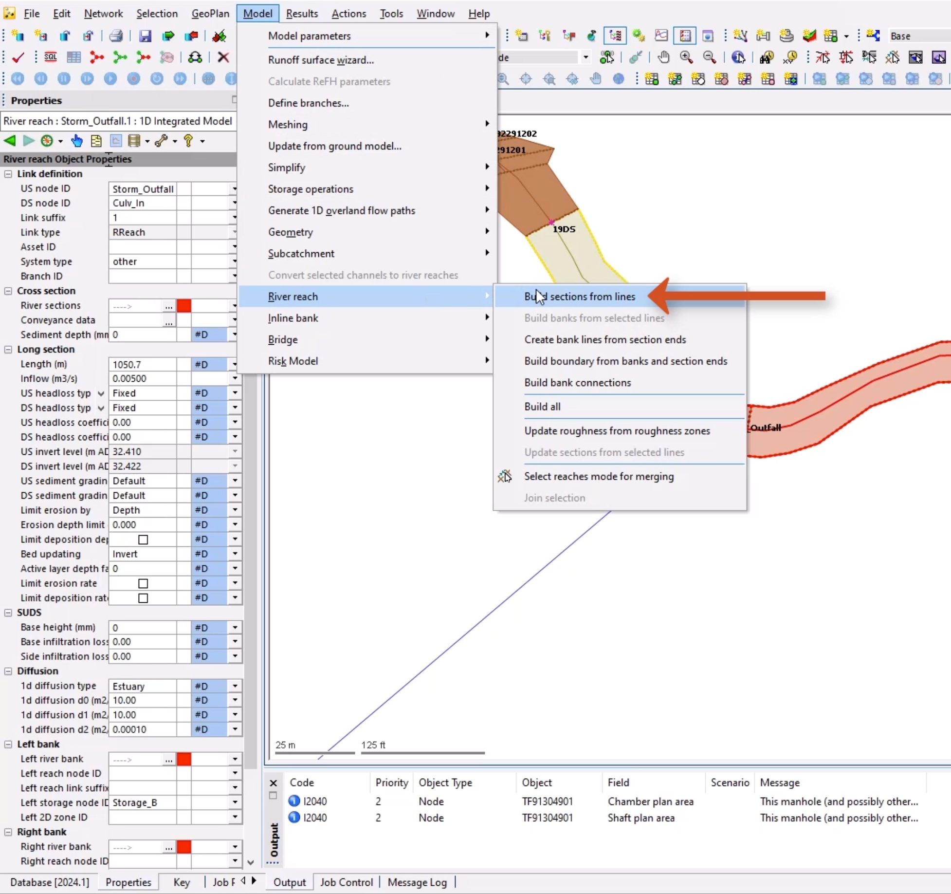
- In the warning popup, select OK.
There is still one validation warning for the River sections field.
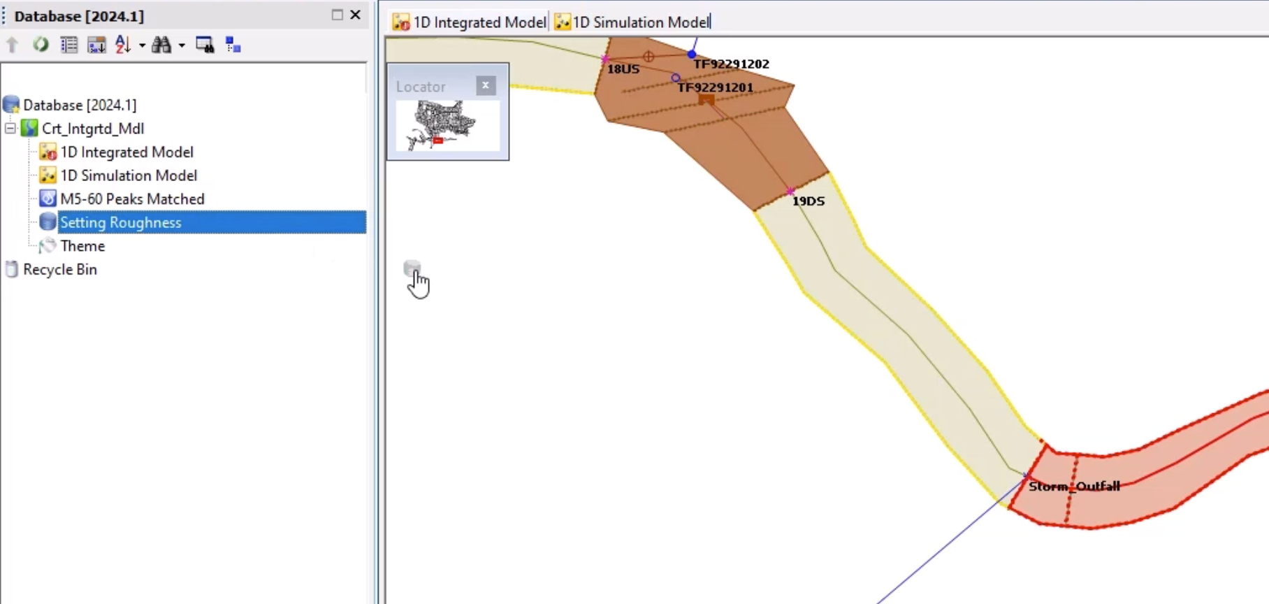
- From the Database, drag the Setting Roughness SQL onto the GeoPlan. This updates the missing roughness values.
With the validation warnings corrected, check the downstream invert level of the conduit:
- From the GeoPlan Tools toolbar, click the Long Section pick tool.
- On the GeoPlan, click Storm_Out1.1.
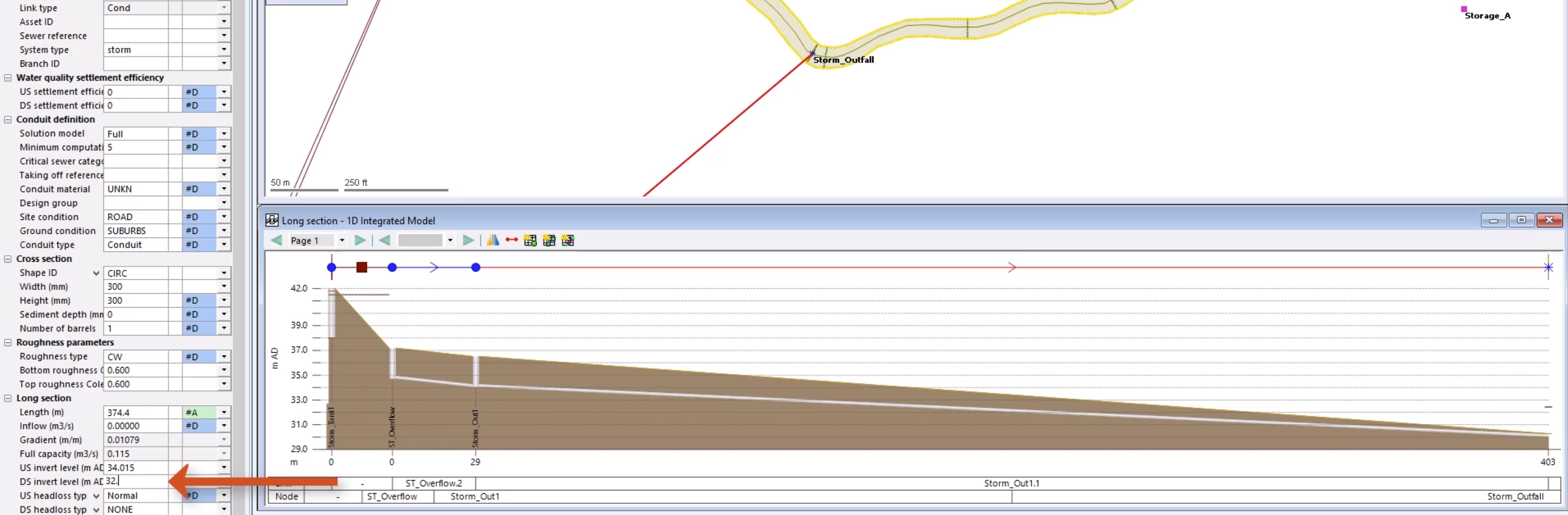
Note: It is below the bed level of the river and must be corrected. Outfall levels are often assumed where data is not available and can require correction.
- In the Properties window for Storm_Out1.1, set the DS invert level (m AD) to 32.500.
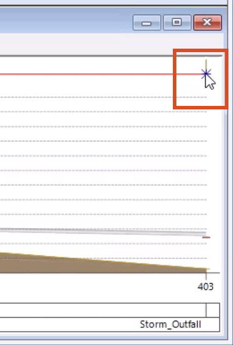
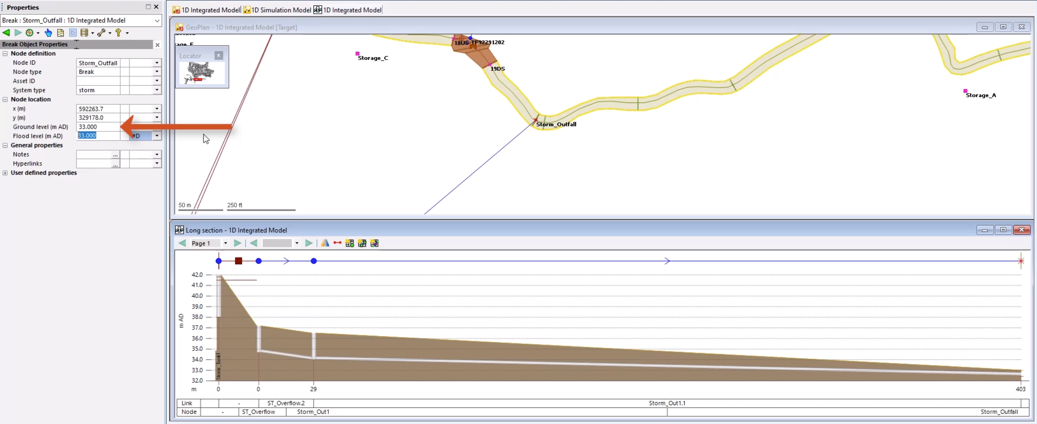
- In the long section, select the Storm_Outfall node.
- In the Properties window, set the node Ground level to 33.000 m AD.
- Click Validate to make sure there are no errors in the network.
Several warnings appear, but ignore these for now.
- Click Commit changes to database to save the changes.
- Add a comment, such as “Connected outfall locations into the river reaches”.
- Click OK.
The two networks are now connected as an integrated model. Flow can now transfer between the urban drainage network and the river channel via the created connection points.