Making changes to mechanical systems
Make and review changes to connector configurations in a mechanical system.
Tutorial resources
These downloadable resources will be used to complete this tutorial:
Step-by-step guide
Make and review changes to connector configurations in a mechanical system.
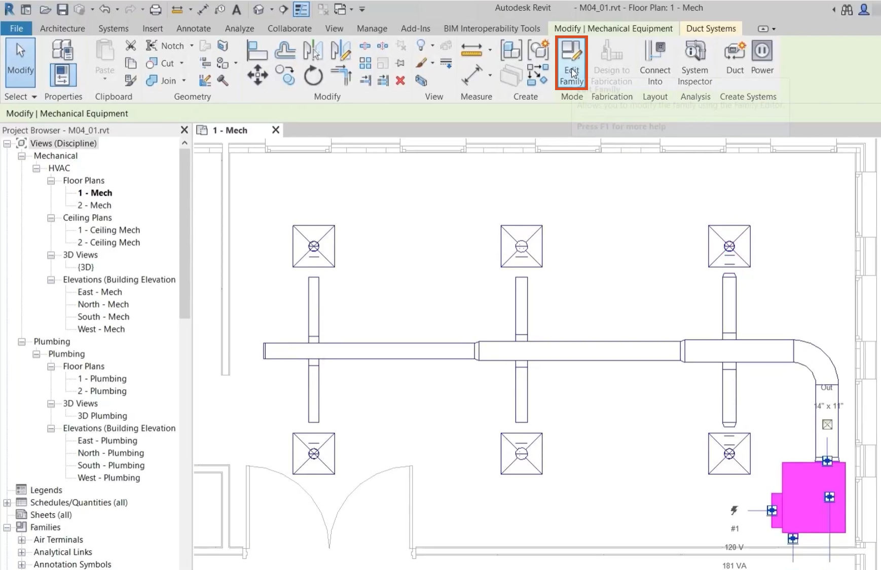
- Open the project M04_01.rvt.
- Ensure that the current view is HVAC > Floor Plans > 1 – Mech.
- Select the VAV unit.
- On the contextual ribbon, click Edit Family to open it in the Family Editor.
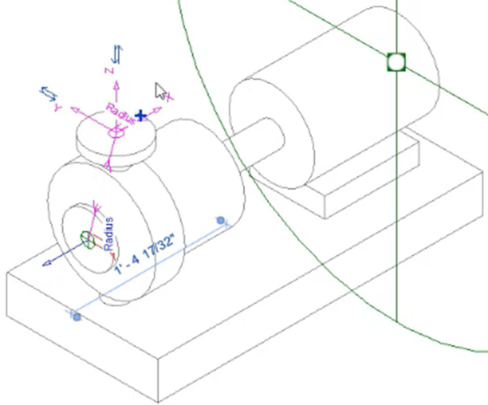
- Select the connector at the front of the unit.
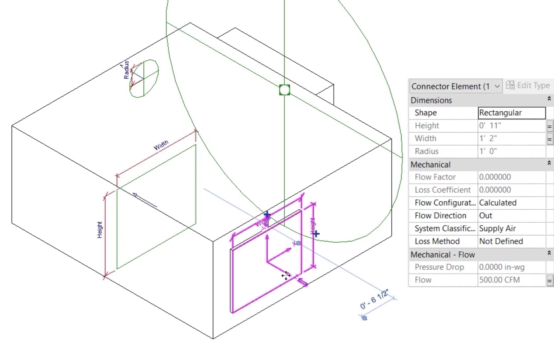
In the Properties palette, note the following:
- The System Classification parameter determines that the VAV unit can be connected to a supply air system.
- The Flow Direction is set to OUT at the connector, meaning that the air flows out of the VAV unit.
- The Flow Configuration is set to Calculated; the total flow rate for all air terminals connected to this equipment will be calculated at this point.
- The connector size is associated with relevant family parameters, indicated by the small equals symbols next to the Height and Width fields.
- Close the family without saving the changes.
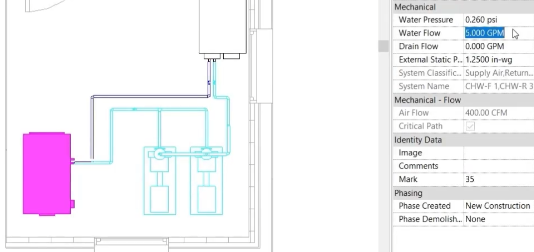
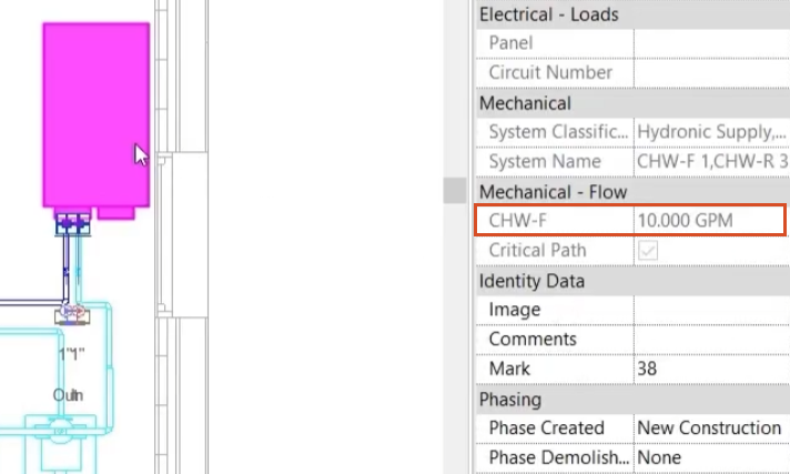
- Select the air handling unit as shown to confirm in Properties that the water flow rate is 5 GPM. This a preset value altered by the user.
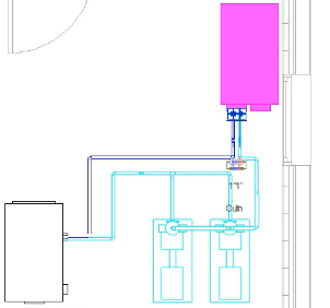
- Select the chiller as shown and confirm in Properties that the chilled water flow rate is also 5 GPM. This a calculated value determined by the flow rate entered at the air handling unit.
- Select the air handling unit again.
- In Properties, change the Water Flow rate to 10 GPM.
- Select the chiller to confirm the updated value.
- Select each of the pumps in turn and note the Calculated Flow rates.
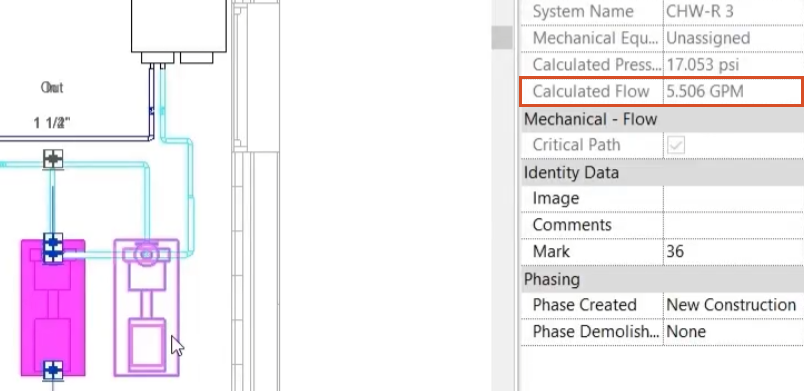
The total flow rate in the system is divided between the pumps, but not equally.
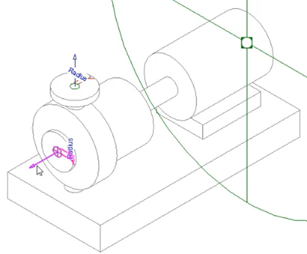
- Open the pump in the Family Editor.
- Select the IN connector.
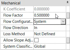
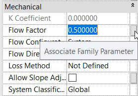
- Change the flow configuration to System and note that the Flow Factor parameter is now active.
Associate the Flow Factor parameter, so that the value can be changed at the pump within the project:
- Next to the Flow Factor parameter value, click the small gray square.
Since the required parameter does not exist, create a new one:
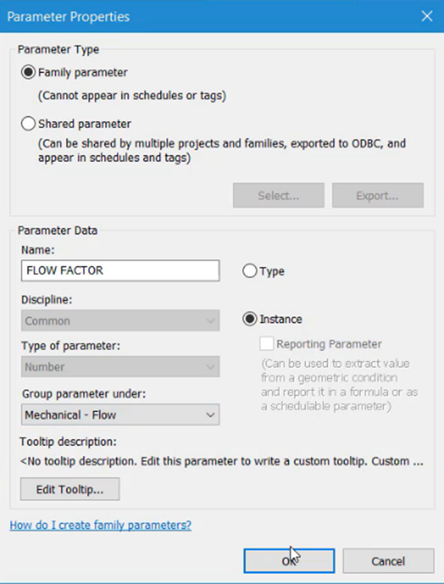
- In the Associate Family Parameter dialog box, click New Parameter.
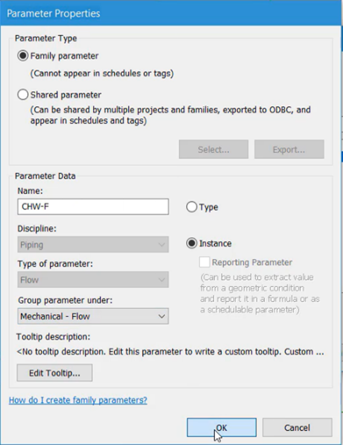
- In the Parameter properties dialog box, enter a parameter Name, such as "Flow Factor".
- Select Instance.
- In the Group parameter under drop-down, select Mechanical – Flow.
- Click OK to close both dialog boxes.
Now, associate the new Flow Factor parameter with the OUT connector:
- On the pump, select the OUT connector.
- In Properties, change the Flow Configuration to System.
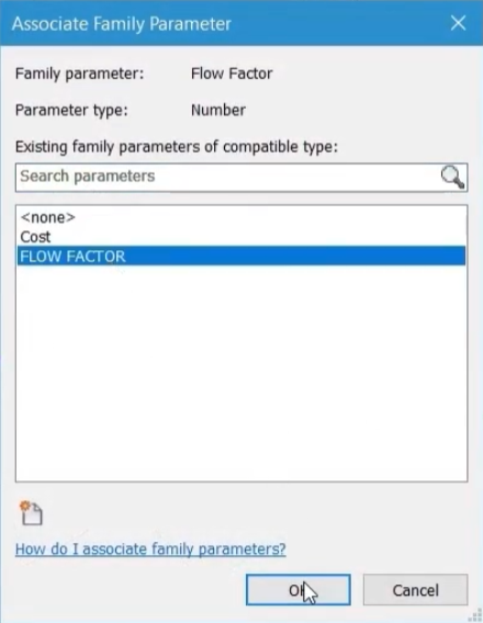
- Open the Associate Family Parameter dialog box.
- Select the Flow Factor parameter created in the previous step.
- Click OK.
Next, create a chilled water flow parameter and associate the parameter for each connector:
- On the pump, select the IN connector.
- In Properties, next to Flow, click Associate Family Parameter.
- Click New Parameter.
- Name the new parameter "CHW-F", for chilled water flow.
- Select Instance.
- For Group parameter under, select Mechanical - Flow.
- Click OK to close both dialog boxes.
- Select the OUT connector.
- Next to Flow, click Associate Family Parameter.
- Select the new CHW-F parameter.
- Click OK.
- To load the family back into the project, on the ribbon, click Load into Project.
- Select Overwrite the existing version.
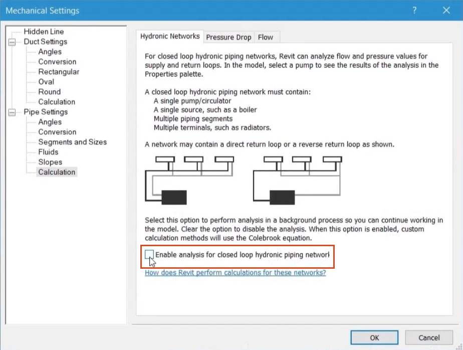
- On the Systems tab, HVAC panel, click the Mechanical Settings dialog launcher.
- Deselect Enable analysis for closed loop hydronic piping networks.
- Select each of the pumps to ensure that the new flow factor parameter is set to 0.5, which will divide the flow equally between the two.
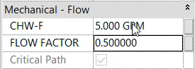
A review of the new CHW-F parameter confirms that the total flow rate in the system is now equally divided between the two pumps.
- Select various sections of pipe in the system to confirm the even and correct distribution of the flow set at the air handling unit.
- Save the project.