Validating the network
Identify the various validation types that you can run, as well as how to examine errors, warnings, and information messages.
Tutorial resources
These downloadable resources will be used to complete this tutorial:
Step-by-step guide
Identify the various validation types that you can run, as well as how to examine errors, warnings, and information messages.
ICM validation tools can be used to examine a network or object properties for missing values, errors, and inconsistencies. A network must be successfully validated before it can be used in a simulation. During validation, the network is checked for errors and values that may affect simulation results or would make it impossible to run.
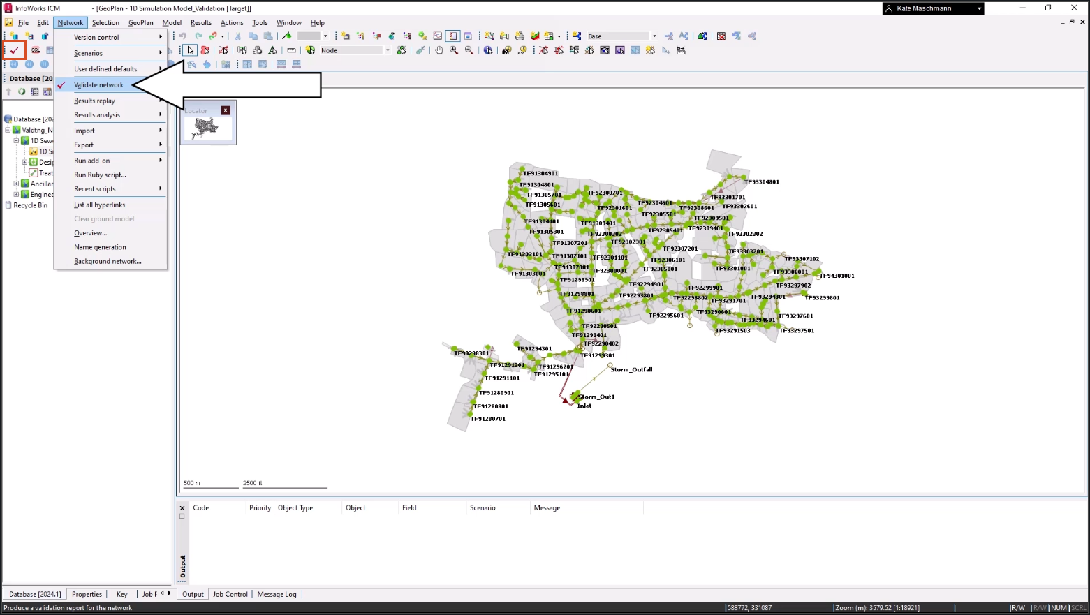
To run a validation:
- On the toolbar, click Validate. Or, from the Network menu, select Validate network.
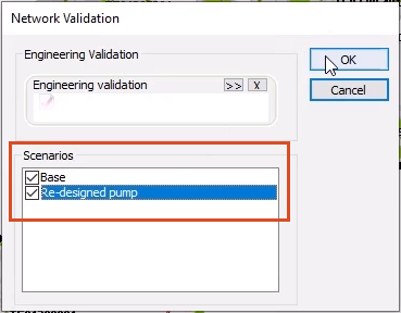
- In the Network Validation dialog box, in the Scenarios list, select the Base scenario or the scenarios that you want to validate.
- Click OK.
Notes:
- Multiple scenarios can be validated simultaneously.
- For large networks, the validation can take some time.
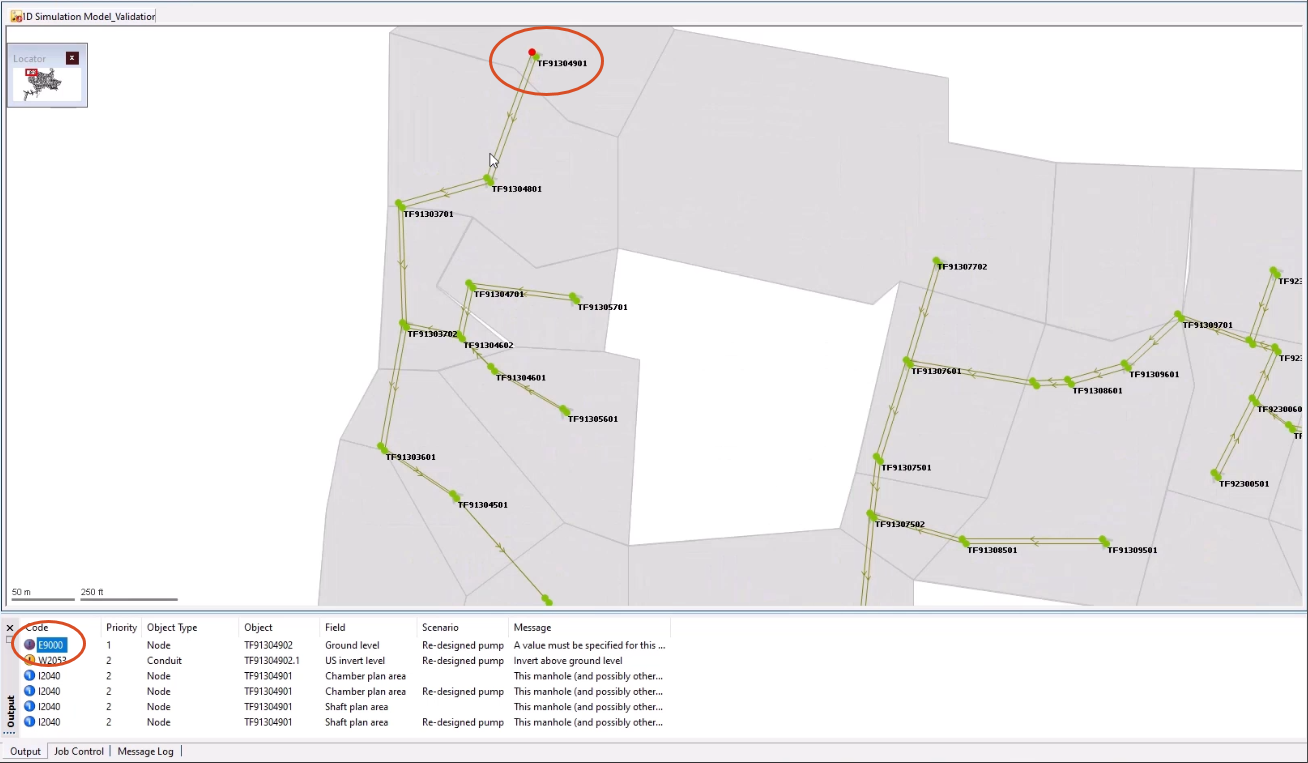
Once the validation is complete, the Output panel appears. Messages are color-coded into three distinct groups:
- Red error messages indicate that action is required before a run can take place. Typically, because information is missing from a field.
- Yellow warning messages indicate that action might be required, but the run can be run. This could mean the results are not realistic.
- Blue messages indicate change details, but no action is needed. For example, the minimum simulation node area may override the set node area.
- Use the Output window options to investigate the corresponding fields and make corrections where needed.
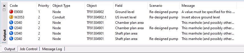
For each warning, the Output window displays information such as the object name and type, as well as a description of the problem.
- Click an item to highlight that network object in the GeoPlan window.
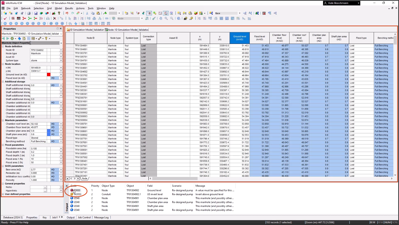
- Double-click the error or warning that you wish to investigate in more detail.
The appropriate grid window is displayed, with the relevant field selected. Also, the corresponding property sheet is displayed in the Object Properties window:
- Fix the errors.
- Rerun the validation.
IMPORTANT:
- A model can be committed without passing the validation. However, it must pass validation in order to use that network in a simulation.
- To help solve errors before you run a Network Validation, an in-line validation is automatically performed as data is added, removed, or edited.
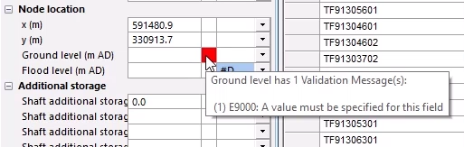
- Color-coded validation errors or warnings (like Network Validation errors) are displayed in the Object Properties window, Validation column.
- Hover your cursor over a validation icon to display the details of the validation error, such as the name of the network object where the anomaly occurred, as well as the cause of the error or warning.
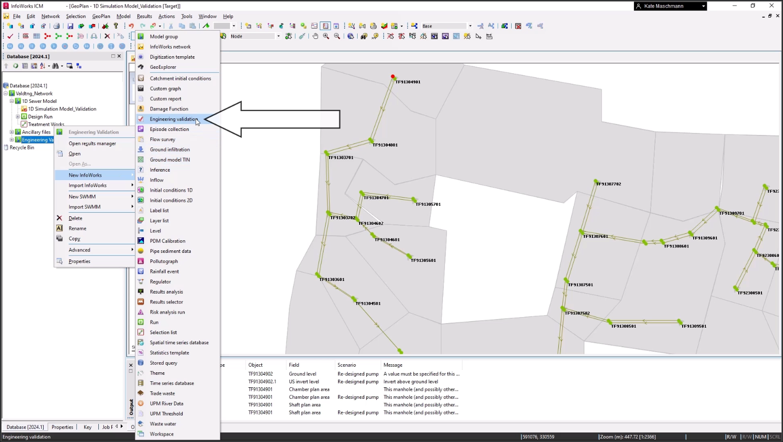
ICM offers an additional level of validation called Engineering Validation. It checks for data that is not consistent with expected engineering values, for example, conduits which have a negative gradient. You can apply either a set of default validation rules or your own modifications to these rules. These checks are carried out in addition to the normal validation, if they are specified in the Network Validation dialog box.
To set up an Engineering Validation item:
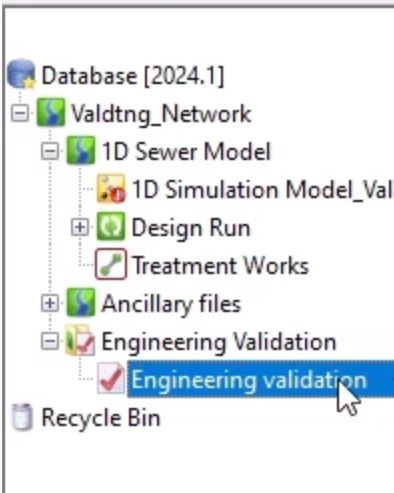
- In the Main Database, right-click Engineering Validation Group and select New InfoWorks > Engineering validation.
- In the New Name – Engineering validation pop-up, enter a name, and then click OK.
- Double-click your new Engineering Validation item to open it.
- The Built In tab displays default validation rules. You are not able to add rules here, but existing rules can be switched on and off, and threshold values used by the rules can be changed.
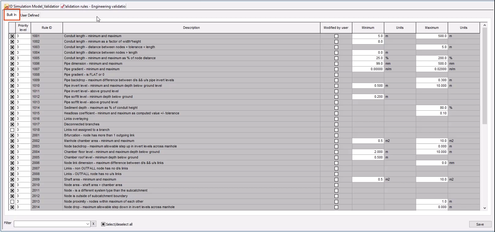
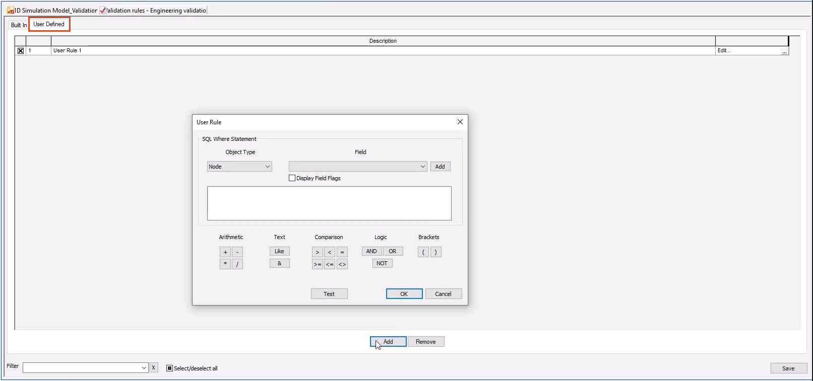
- The User Defined tab allows you to create user-defined validation rules using a simple syntax, similar to SQL statements.
- Click Add to open the User Rule dialog box, where you can build specific rules. InfoWorks ICM includes an editor that allows you to easily build up your own rules without any knowledge of SQL.