Advanced tagging options
Create a new tag to display additional design data.
Tutorial resources
These downloadable resources will be used to complete this tutorial:
Step-by-step guide
Create a new tag to display additional design data.
- Open the project M05_02.rvt.
- Ensure that the current view is HVAC > Floor Plans > 1 – Mech.
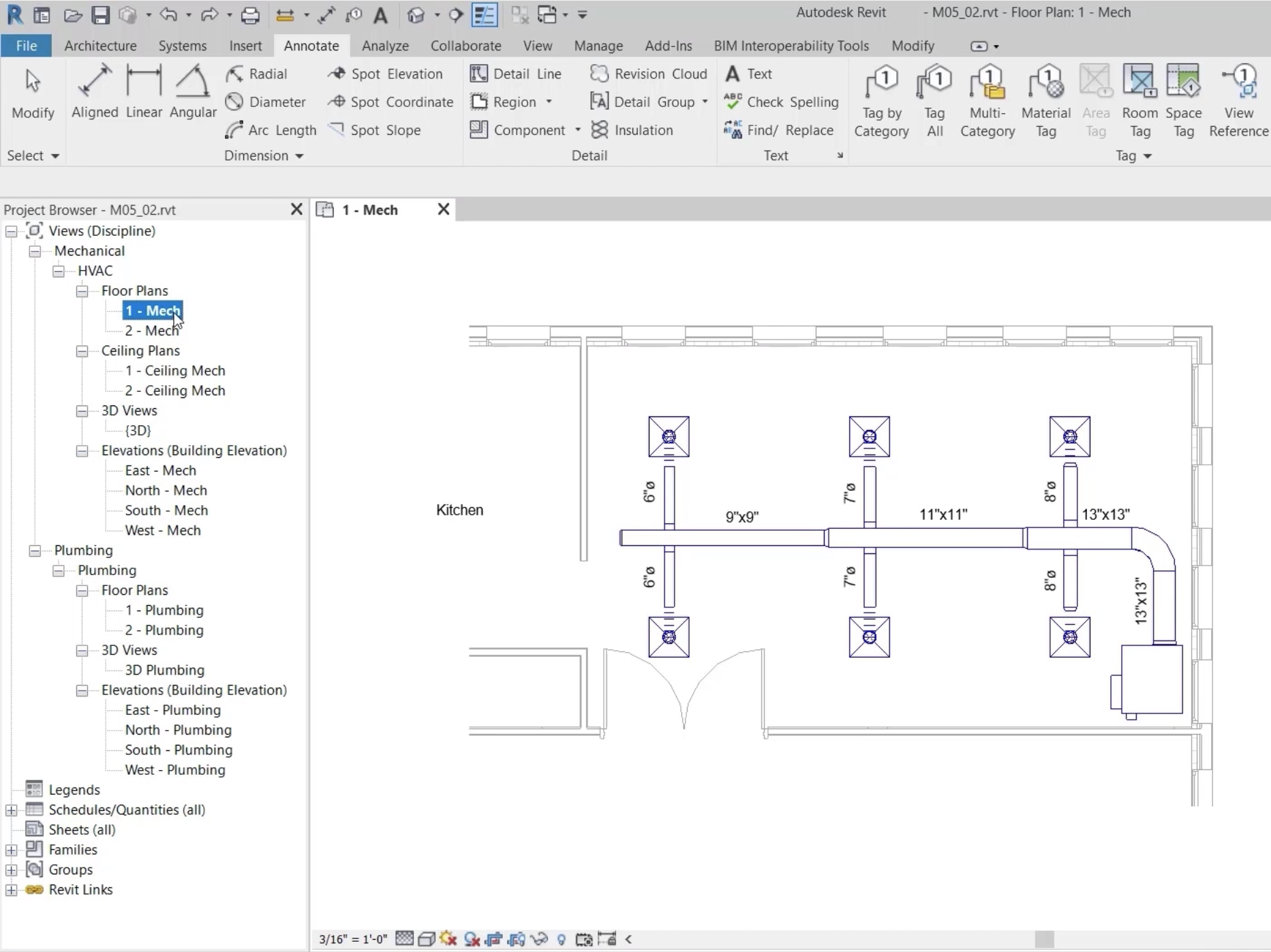
- In the system, select one of the duct size tags.
- On the ribbon, click Edit Family.
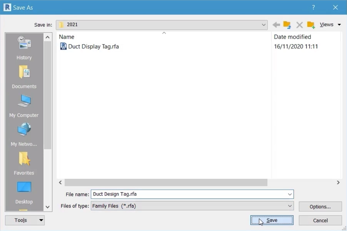
- Select File > Save As > Family.
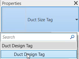
- Save the duct size tag in the desired location as "Duct Design Tag".
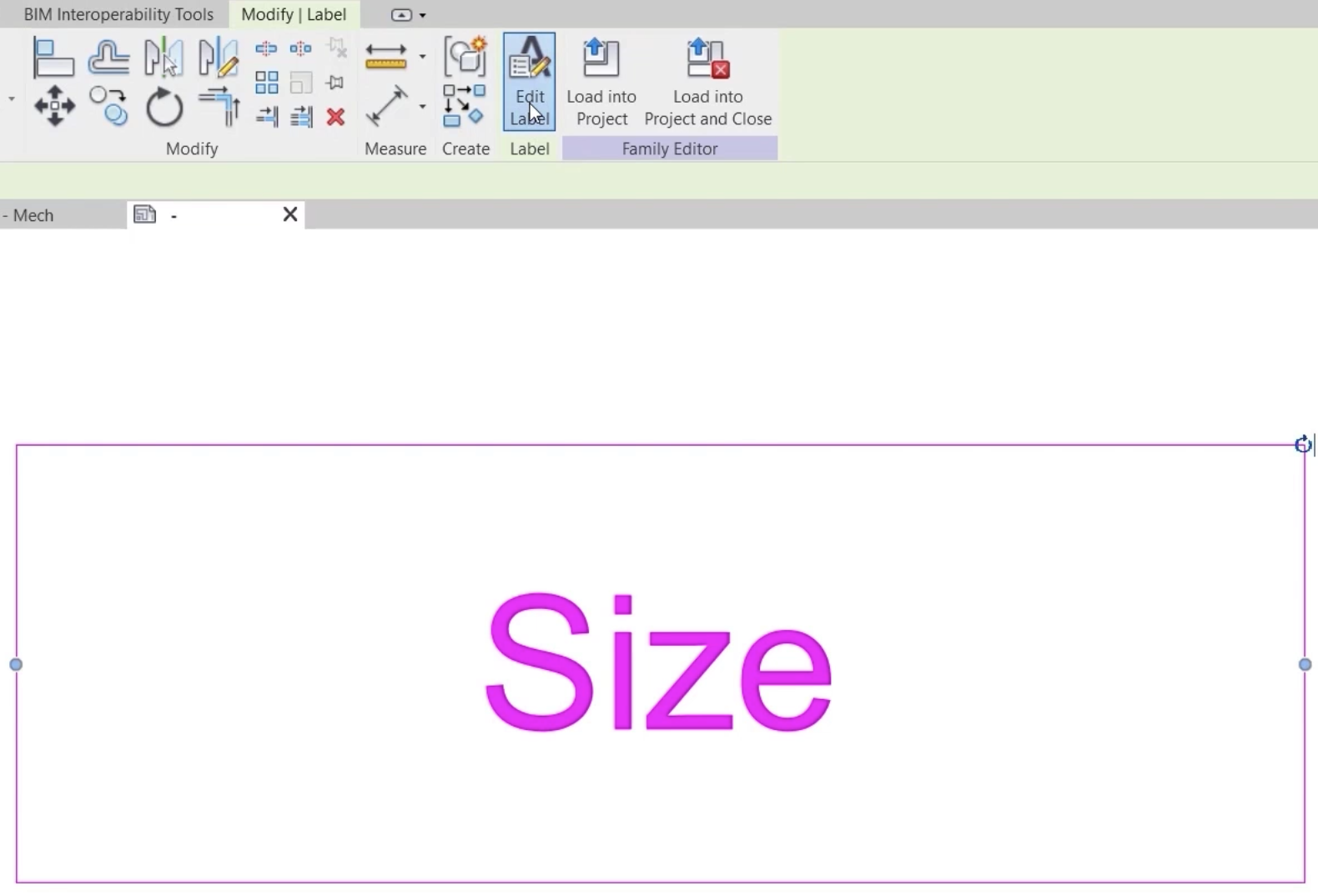
- Select the label.
- On the Modify | Label contextual ribbon tab, click Edit Label.
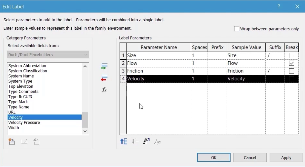
- In the Edit Label dialog box, from the list of available parameters, select Flow.
- Click the green arrow to Add it to the Label Parameters.
- Repeat these steps to add Friction and Velocity to the Label Parameters.
To alter the layout of the data in the tag:
- Click in the Suffix field of the size parameter.
- Press SPACEBAR, then type a forward slash (/).
- For the Flow parameter, select Break.
- In the Suffix field of the Friction parameter, press SPACEBAR, then type a forward slash (/).
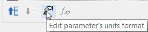
- If required, click Edit parameter's units format to edit the units, unit symbol, and number of decimal places for specific parameters; otherwise, the default project units will be used.
- Click OK to close the dialog box.
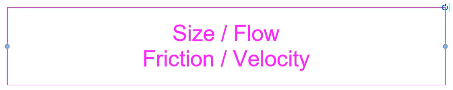
- Use the grips to increase the size of the box around the label to adjust the layout as shown.

- On the ribbon, click Load into Project.
- Select one of the visible duct size tags.
- In the Type Selector, select the new Duct Design Tag.
- Use the move grip to reposition the tag as needed.
- If the information in the tag is not displayed correctly, in the Family Editor, increase the length of the box around the label, as shown.
- Save the tag.
- Click Load into Project.
- Select Overwrite the existing version.
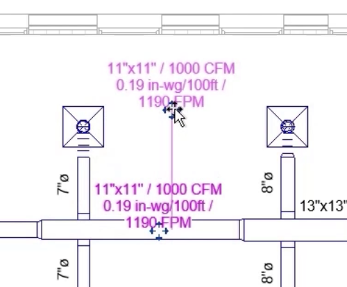
The information shown in the tag should now be displayed correctly.
- Select the new duct design tag.
- From the Options Bar, select Leader.
- Set the leader option to Free End.
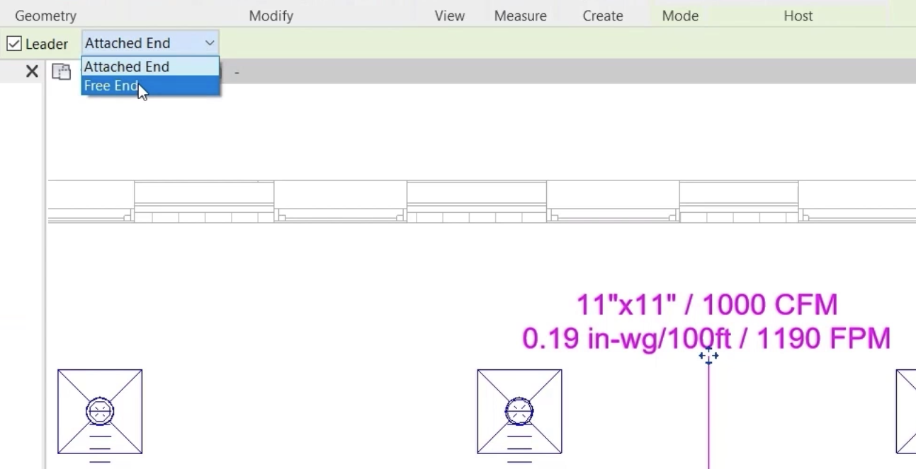
- Move the free end of the leader along the length of the duct and observe the changes in values shown at the tag.
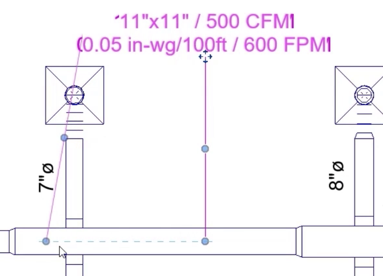
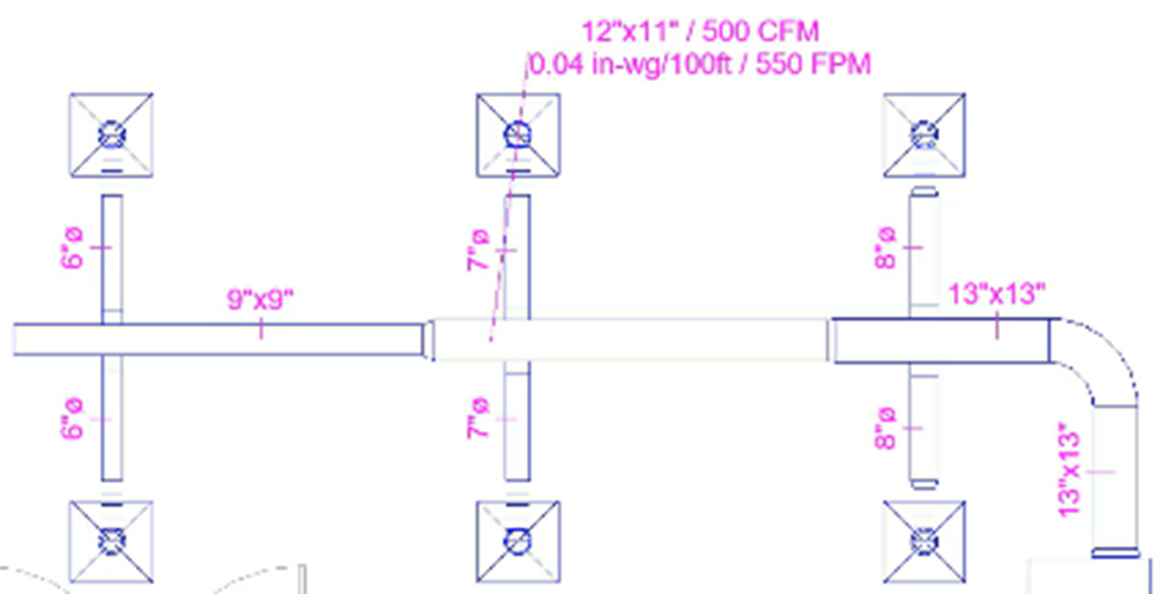
The tag values also update if a change is made to the duct properties.
- Select the tagged section of duct.
- Change the Width to 12ʺ and note the changes in tag values.
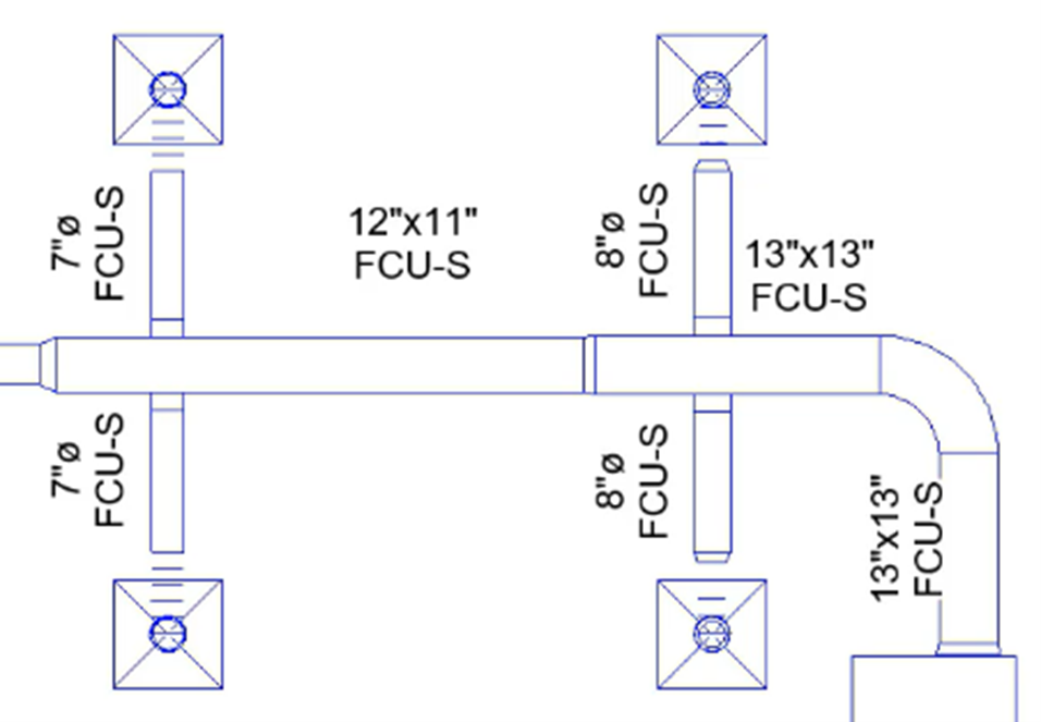
The Duct Design Tag may not be suitable for presenting on final drawings, so other custom tags can be created and applied.
To apply a different, previously created tag to all of the tags in this view:
- Select all tags.
- From the Type Selector, select the new tag—in this case, Duct Display Tag.
The Duct Display Tag shows the duct size and the system name.
- Reposition the tags as required.
- Save the project.