Informed Design BIM definition workflow - MEP connectors
Learn how to use the MEP connector options in the Informed Design BIM definition add-in to add cable tray, conduit, duct, pipe, and electrical connectors when publishing configurable Inventor models to Informed Design. Discover how MEP connectors will be included in the loadable Revit families (.rfa) generated when using the Informed Design add-in for Revit.
Step-by-step guide
Revit MEP Connectors enable the calculation of loads for lighting, HVAC, and power within a Revit project. Revit MEP Connectors can be defined in the Inventor model. When published to Informed Design or exported to RFA, the Revit loadable family will contain MEP connectors.
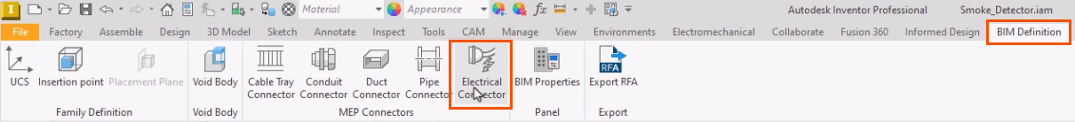
The MEP connectors can be accessed on the Revit BIM Definition tab of the ribbon, in the MEP Connectors panel.
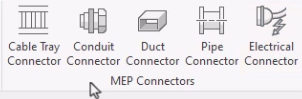
The options encompass multiple disciplines and include Cable Tray and Conduit Connectors for wiring, Duct Connectors for air handling systems, Pipe Connectors for fluids and gases, and Electrical Connectors for power and data.
In this example, add an electrical connector to a smoke detector model.
- On the BIM Definition tab, MEP Connectors panel, click Electrical Connector.
- In the model, select a face to position the connector.
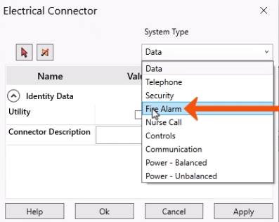
- In the Electrical Connector dialog box, select the appropriate System Type, such as Fire Alarm.
Selecting Utility provides access to the connector for civil engineering applications when exporting the model from Revit via an ADSK file. In this case, leave Utility deselected.
- Type a Connector Description, or, in this example, in the Formula column, click Add to connect the field to a Parameter or iProperty.
This allows the value to be modified for each variant.
- In the Formula dialog box, from the User parameters, select Connector_Description.
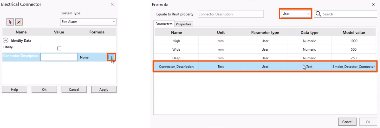
- Click OK.
- Back in the Electrical Connector dialog box, click OK again.
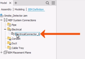
The connector is now created and added to the BIM Definition browser.
- In the BIM Definition browser, expand MEP System Connectors > Electrical.
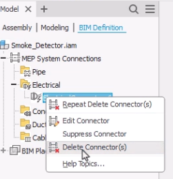
- Right-click the connector to edit, suppress, or delete the connector.
Once it is published, the smoke detector family can be loaded into the Revit project using Informed Design.
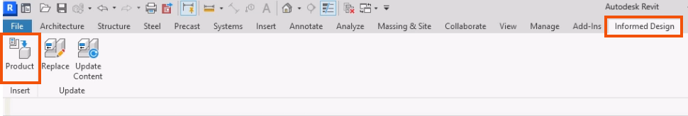
- With the Revit project open, click the Informed Design tab.
- On the Insert panel, click Product.
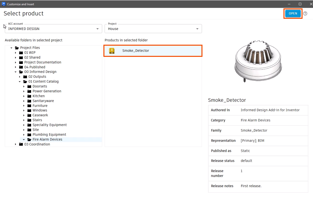
- In the Customize and Insert dialog box, select a product to add. In this example, select Smoke_Detector.
- Click Open.
- Select the BIM representation.
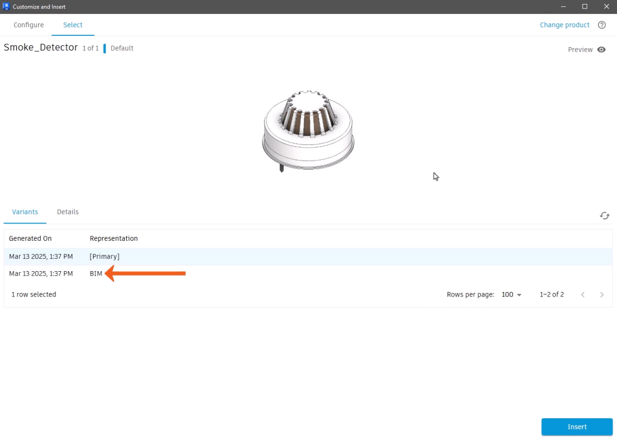
- Click Insert.
- Click in the model to place the smoke detector family.
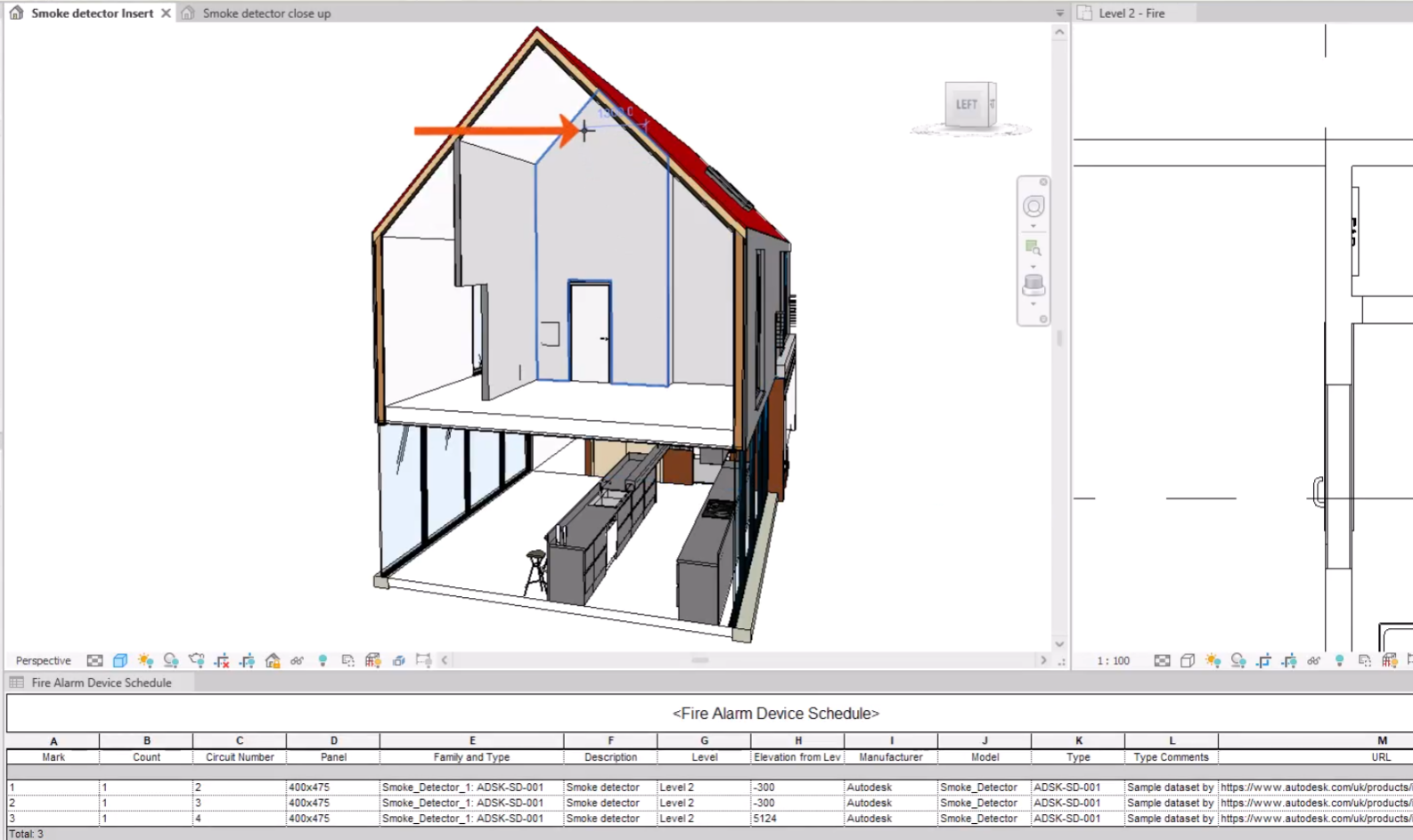
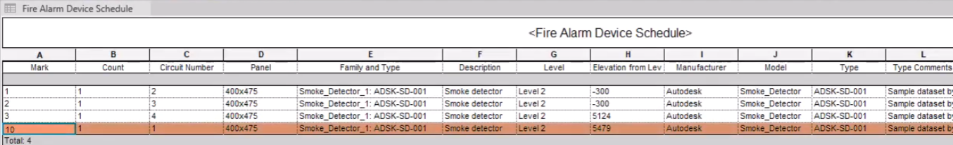
Once it is placed, select the connector to add it to a circuit. The panel details for the circuit can be seen in the Fire Alarm Devices schedule.