Informed Design for Inventor - an introduction to Codeblocks for form rules
Discover how Codeblocks in Informed Design can be used to define the layout of the input form that will be used in Revit to configure the manufacturing model.
Step-by-step guide
Informed Design utilizes rules created from Codeblocks to manage the input values and options for the Informed Design form.
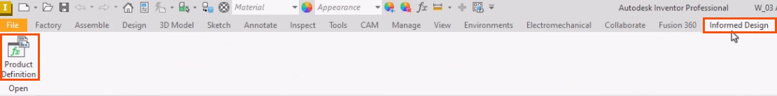
To access Codeblocks, begin with the Inventor project open.
- On the ribbon, select the Informed Design tab.
- Click Product Definition.
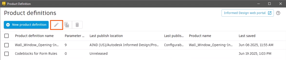
- In the Product definitions list, select the appropriate option.
- Click Edit.
- Select the Rules tab.
- Select the Input workspace.
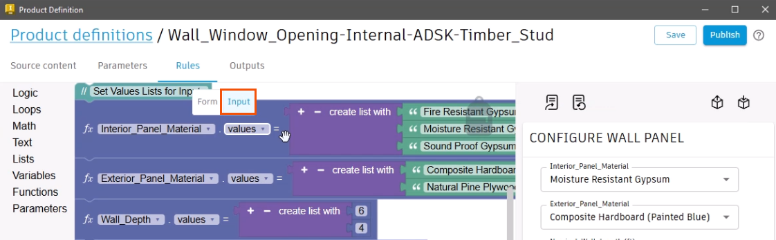
The logic contained in the Codeblocks is used define and restrict the options, values, and combinations of values that can be entered into the form, helping to ensure that only valid, manufacturable product variants are defined. For example, the logic can configure a drop-down so that only specific options can be selected, or it may set maximum or minimum allowable values for an input.
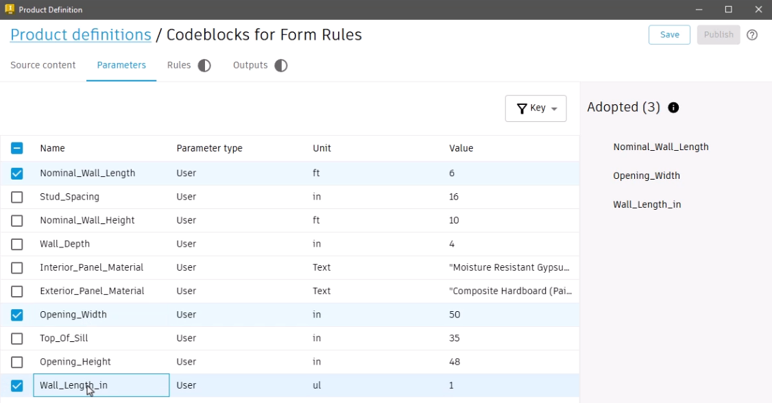
Before designing a form, it is important to first adopt the Inventor parameters:
- Click the Parameters tab.
The product definition automatically lists the Inventor User parameters, but other lists are available.
- In this case, expand the drop-down and select Key parameters.
- Select the Inventor parameters to adopt as Informed Design parameters; for example, select Nominal_Wall_Length, Opening_Width, and Wall_Length_in.
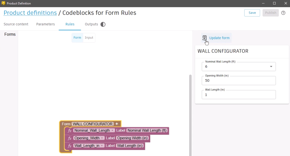
- Select the Rules tab to open the Form workspace, where adopted parameters display.
The Form workspace is used to design and customize the visible aspects of the Informed Design form, such as organizing and applying names to the input fields.
For this example, make the following changes:
- Remove underscores from the label names.
- Rename the form to “Wall Configurator”.
- Click Update form to view the changes.
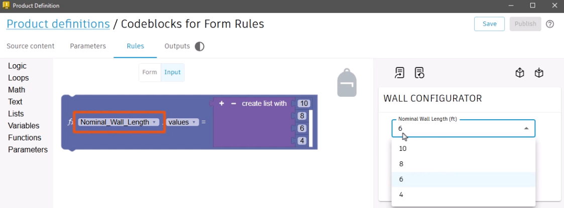
- Select the Input workspace.
The Input workspace is used to build the logic and apply constraints that govern the values and options within the form.
Adopted parameters that contain a list are automatically added to the Input workspace. In this example, the Nominal Wall Length parameter is added and contains the list of available selections.
The Codeblocks library contains a comprehensive set of code blocks within different categories that are used to build the logic rules that govern the design intent of the Inventor model. These include:
- Logic blocks for the creation of conditional statements,
- Loops blocks for the iteration of code,
- Math blocks to assist with calculations,
- Text blocks for working with strings,
- Lists blocks for working with collections,
- Variables, which are user-created containers to hold data,
- Functions, which can be reused to perform common tasks within a rule, and
- Parameters, which are adopted from the Inventor model.
- Select a category, such as Logic, to view the available blocks.

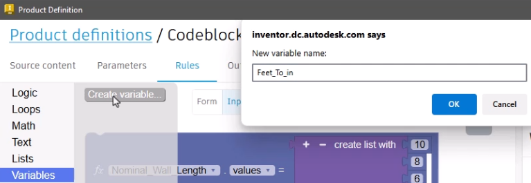
Variables can be created to perform an intermediate calculation that displays in the form, such as a conversion from feet to inches:
- Select Variables > Create variable.
- In the New variable name dialog box, type "Feet_To_in".
- Click OK.
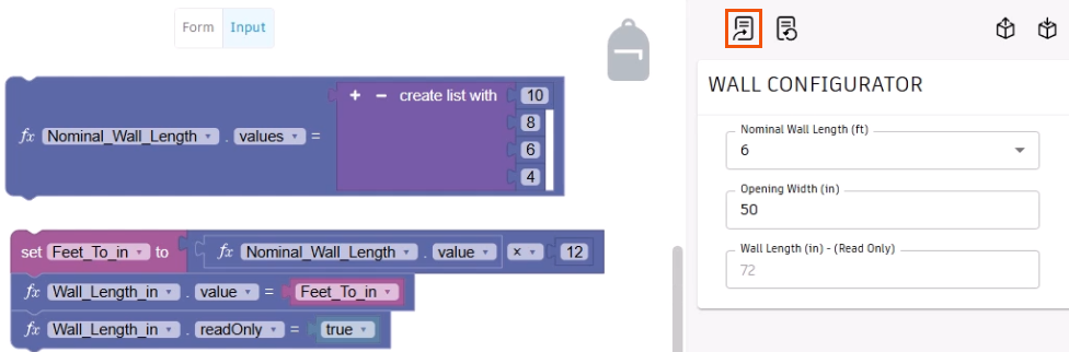
- From the Variables library, drag the new Set Feet_To_in block into the workspace.
- Add an Operation math block, a Nominal Wall Length value parameter block, and a math Number block to the variable block.
- Adjust the blocks so that the logic will multiply the Nominal Wall Length value parameter by 12 to convert it to inches.

A parameter block can be used to map the variable value to an input field and to set it to read-only.
- Add two Nominal Wall Length value blocks below the Set variable block, then adjust them to map to the Wall_Length_in parameter.
- Add the Set Feet_To_in variable block to the first parameter.
In this case, the input is only for information.
- Set the second parameter block to readOnly, and then add a True False logic block with a value of true.
- Click Update form.
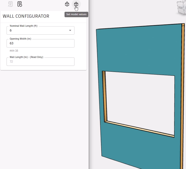
The Wall Length (in) input field in the form automatically converts the Nominal Wall Length into inches and is a read-only field.
The parameter block can also control allowable inputs.
- Add another Nominal Wall Length value parameter block to the workspace, and set it to Opening_Width.
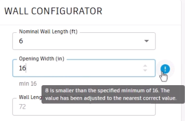
- Adjust the value to min and add a math Number block with a value of 16. This ensures that the opening width is at least 16 inches.

- Update the form.
The label below the input field now communicates the minimum allowable value.
- Enter a value less than the minimum, such as 8, and the input value automatically resets to 16.
- Hover the cursor over the message icon to view the reason for the adjustment.
To set a maximum value for the opening width:
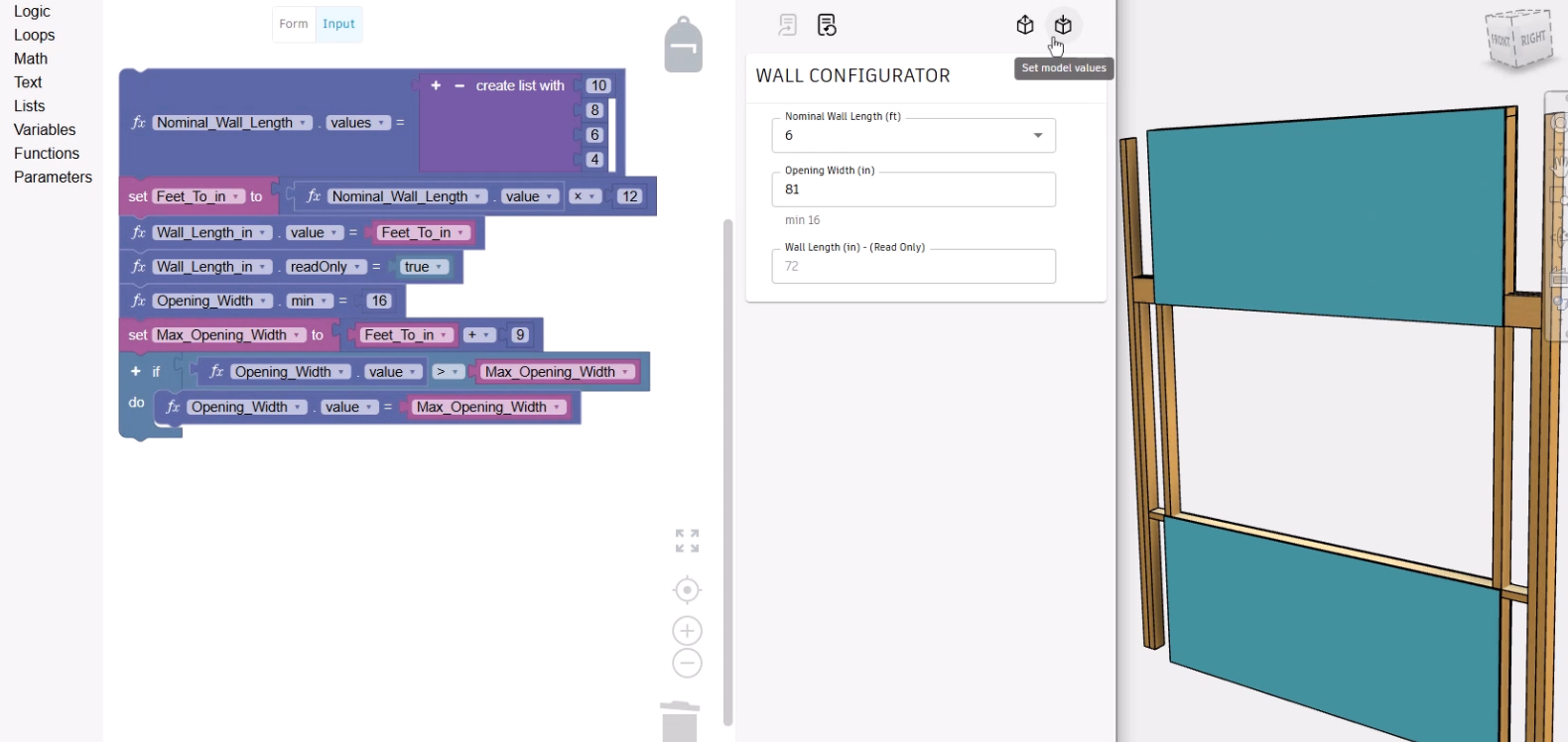
- Create a Variable called Max_Opening_Width and add it to the workspace.
- Add an Operation math block, the Set Feet_To_in variable block, and a math Number block with a value of 9, so that the finished block statement reads Set the Max_Opening_Width to Feet_To_in plus 9.

Next, create logic to ensure that the opening width does not exceed the maximum as calculated by the previously created variable:
- Use the conditional If Do block statement, along with an Operation math block, as well as parameter and variable blocks, to create a block statement that reads if the Opening_Width value is greater than the Max_Opening_Width, then set the Opening_Width to equal the Max_Opening_Width.

- Snap all the code blocks together into one set to organize the workspace.
- Click Update form.
- To test the logic, in the form, enter a value that is above or below the constrained values for Opening Width, such as 999.
The field automatically updates to equal the Wall Length in inches plus 9, or in this case, 81.
- To update the Inventor model, click Set model values.
In the Inventor model, the result shows an unexpected error, since the opening width exceeds the length of the wall in inches.
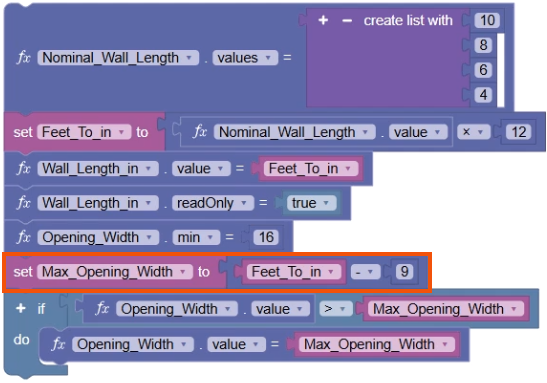
- Review the code blocks to identify the error in the logic.
In this case, the Max_Opening_Width variable is set to add 9 inches, instead of subtracting 9 inches.
- Update the operation to subtraction.
- Click Update form.
- Test the form again by entering an Opening Width value of 999. The value automatically updates to 63.
- Click Set model values.
The Inventor model updates, confirming that the fix is successful.