Creating inline banks
Create inline banks in preparation for connecting 1D and 2D parts of the network.
Tutorial resources
These downloadable resources will be used to complete this tutorial:
Step-by-step guide
The inline bank is a control object that can be used to act as a connection between 1D and 2D parts of the network. The bank line is drawn where the coupling takes place, and the inline bank link is drawn in the direction of flow, so that it intersects the bank line.
- To begin, from the File menu, select Open > Open transportable database.
- Navigate to and select the .icmt file.
- Click Open.
- If a popup appears regarding opening the database as read-only, click Yes.
- In the transportable database window, right-click the top-level folder and select Copy.
- In the popup, click Continue.
- Right-click the Database and select Paste (with children).
- In the Copying pop-up, enable Copy ground models.
- Click Continue.
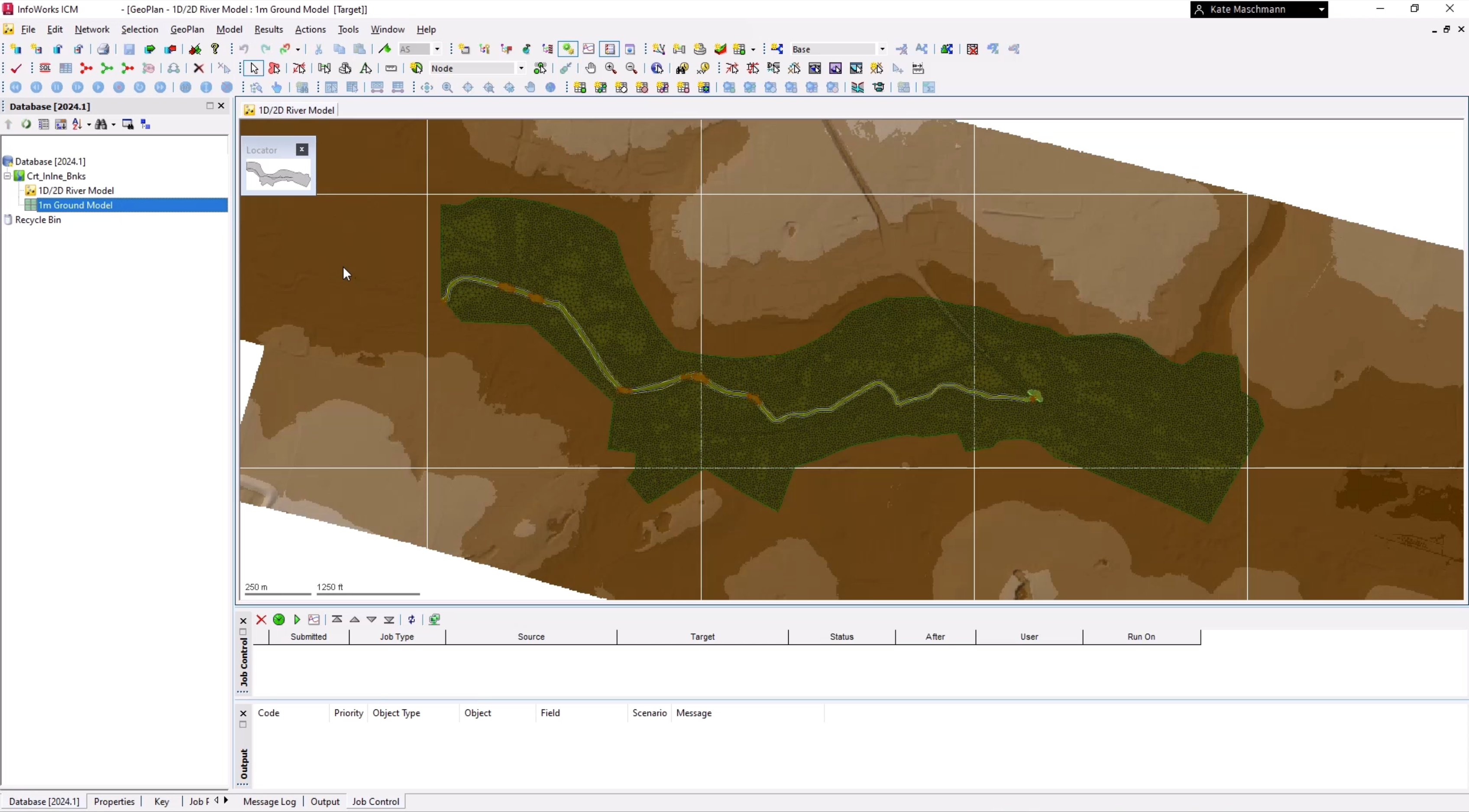
- In the Explorer window, double-click 1D/2D River Model to open it on the GeoPlan.
- From the Database, drag 1m Ground Model and drop it onto the GeoPlan.
To import the bank lines:
- From the Network menu, click Import > Open Data Import Centre to open the ODIC.
- In the Table To Import Data Into drop-down, select Bank line.
- Under Data Source, ensure that the Source Type is set to Raw Shape File.
- Click the More (…) button.
- Navigate to and select the *.shp file—in this example, Bank Lines.shp.
- Click Open.
- Under Field Mapping Configuration, click Auto-Map to search the import file for fields that match.
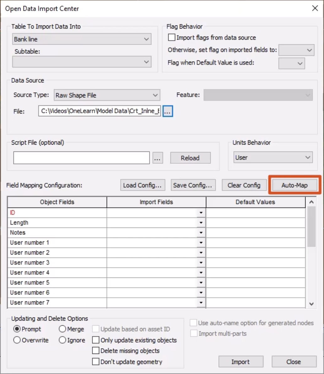
- Click Import.
- Click OK to close the notification.
- Close the ODIC.
- In the GeoPlan Tools toolbar, click Find in GeoPlan.
- Perform a Quick Find for Culv_Out.
- Once the node is located, Close the Quick Find window.
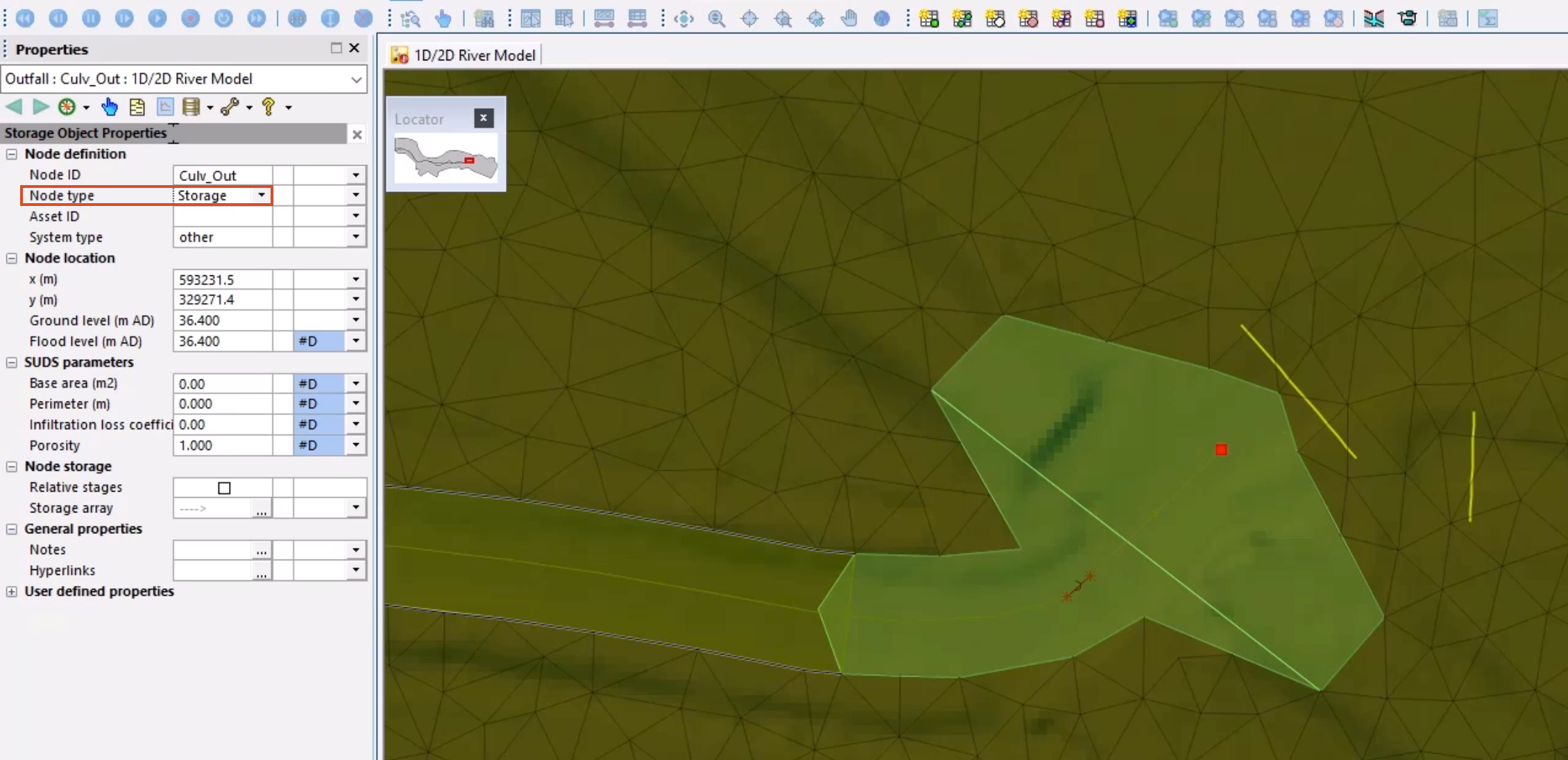
- Double-click Culv_Out to open the Properties window.
- Change the Node type to Storage to prevent flow from being lost at the outfall.
- Zoom out slightly to view the extents of the storage area polygon.
The two imported bank lines, shown in yellow, will be used to create the inline banks.
- From the Windows toolbar, click New 3D network window.
- Use the viewpoint to navigate the 3D representation of the culvert in relation to the ground model.
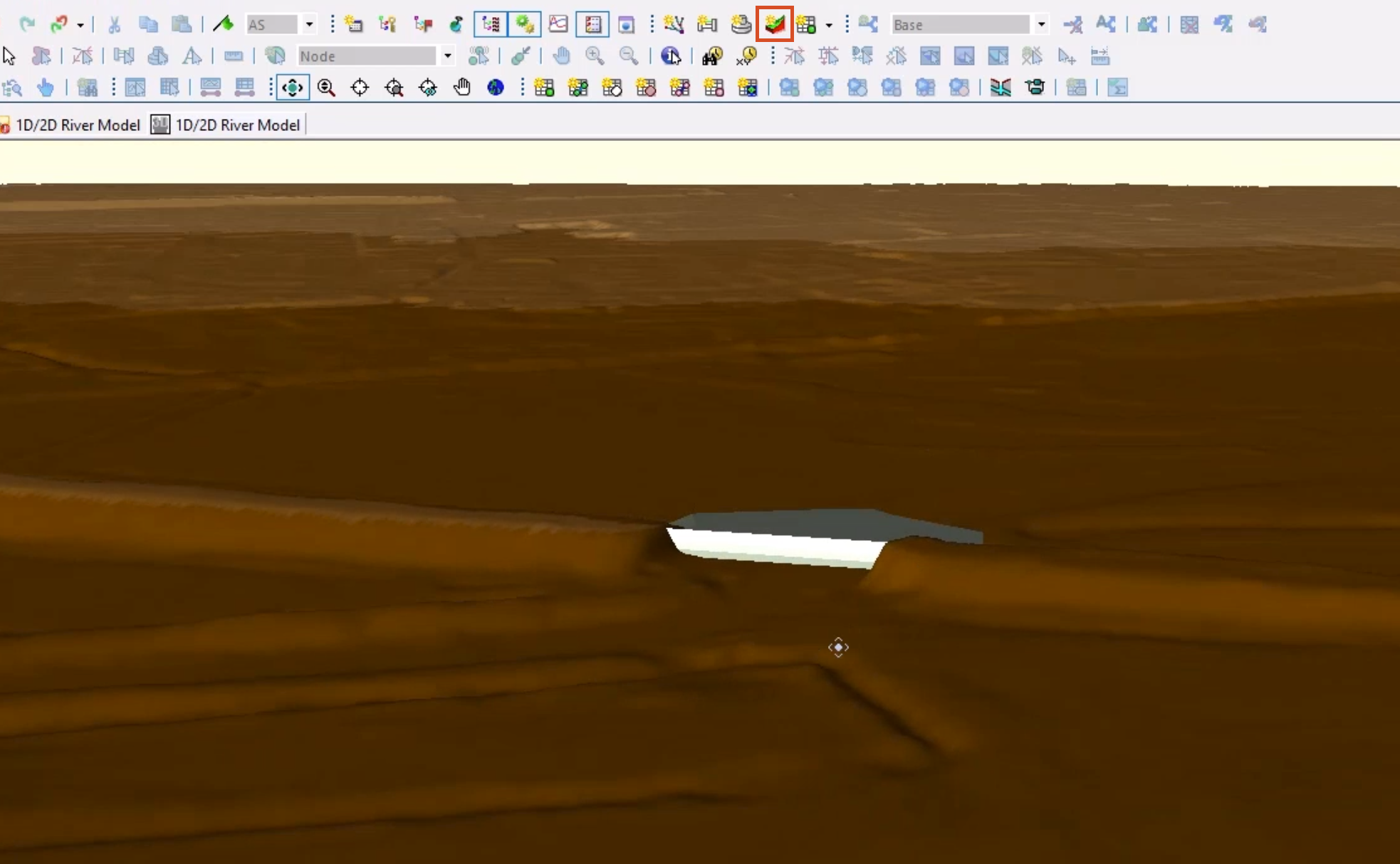
The embankment has been filtered out of the ground model, which is a common issue. If this area were simply meshed, it would allow flow through the gap. The storage area is present to void this area. Notice the area downstream of the river becomes flatter and the channel is less defined, making it more appropriate for 2d representation.
- Close the 3D View window.
Now, create two new outfall nodes on the right-hand side of each bank line:
- From the GeoPlan Tools toolbar, expand the New Object Type drop-down and select Node.
- Click New Object.
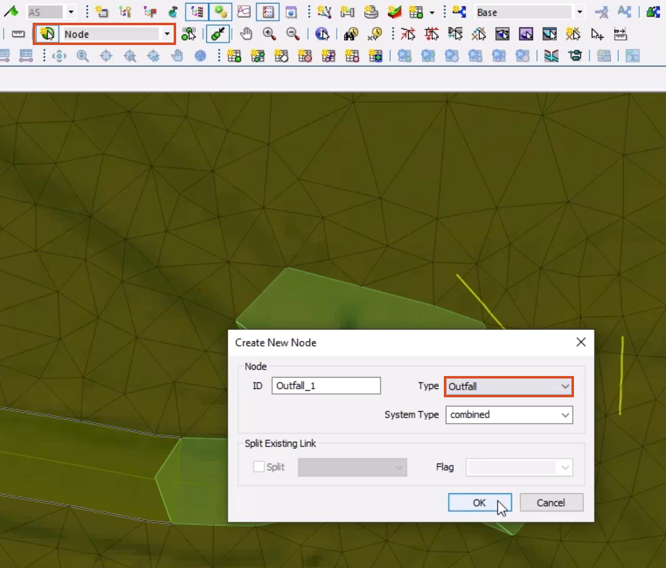
- On the GeoPlan, to the right of the first bank line, click to add a node.
- In the Create New Node popup, add an ID of “Outfall_1”.
- Set the Type to Outfall, being careful NOT to select Outfall 2D.
- Click OK.
- To the right of the second bank line, add another node with an ID of “Outfall_2”.
- In the New Object Type drop-down, select Link.
- Click New Object.
- Draw a link from Culv_Out to the first added outfall node.
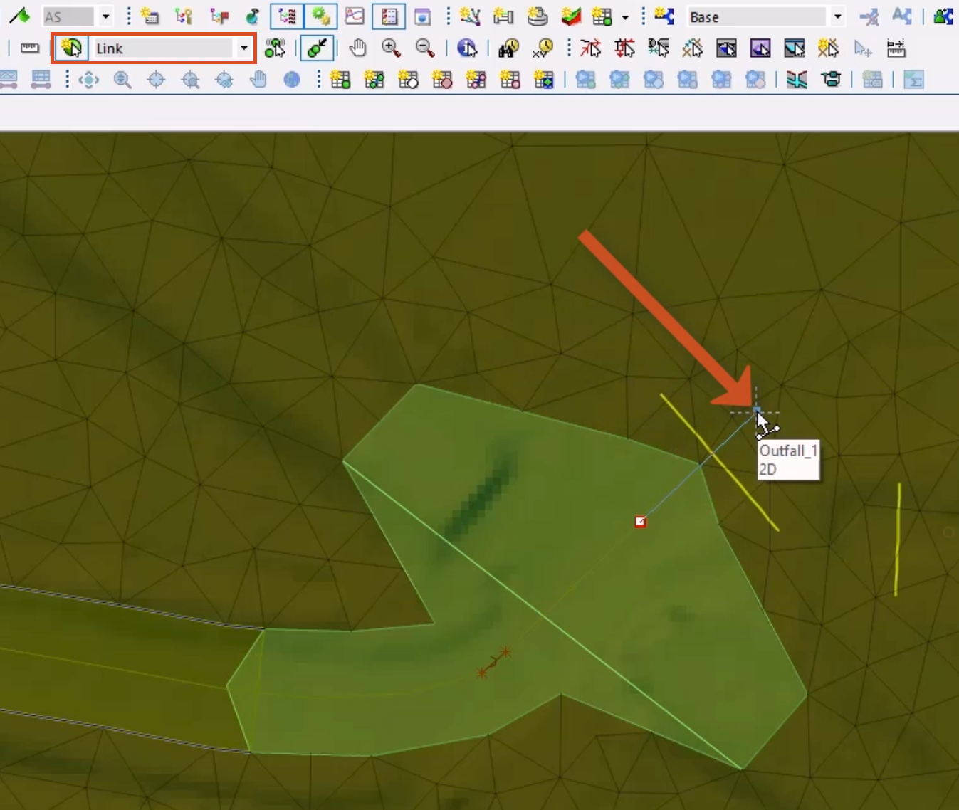
- In the Create New Link popup, set the Type to Inline bank.
- Click OK.
- Repeat steps 40-42 for the second node, drawing the link from Culv_Out to the Outfall_2 node.
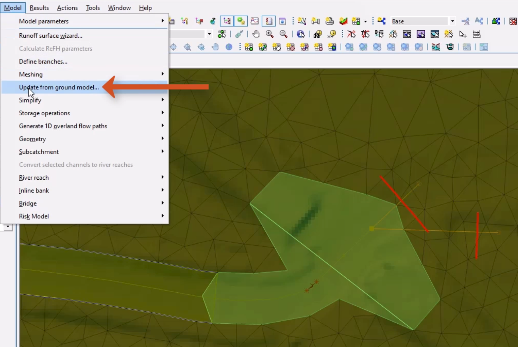
- In the GeoPlan Tools toolbar, click the Selection tool.
- Press and hold CTRL while clicking the two bank lines to select them.
- From the Model menu, select Update from ground model.
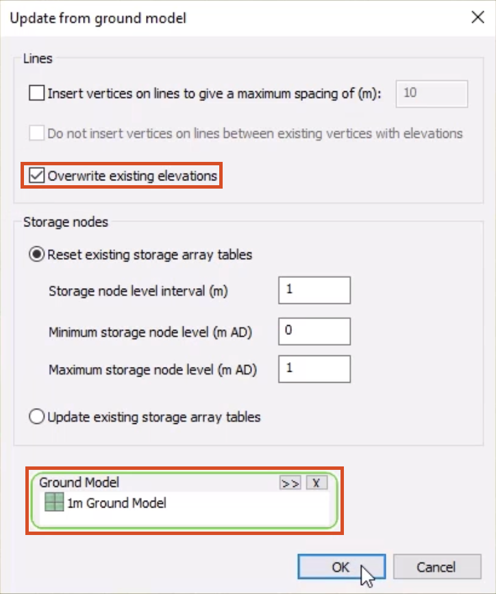
- In the Update from ground model dialog box, enable Overwrite existing elevations.
The Ground Model group box should be automatically populated.
- Click OK.
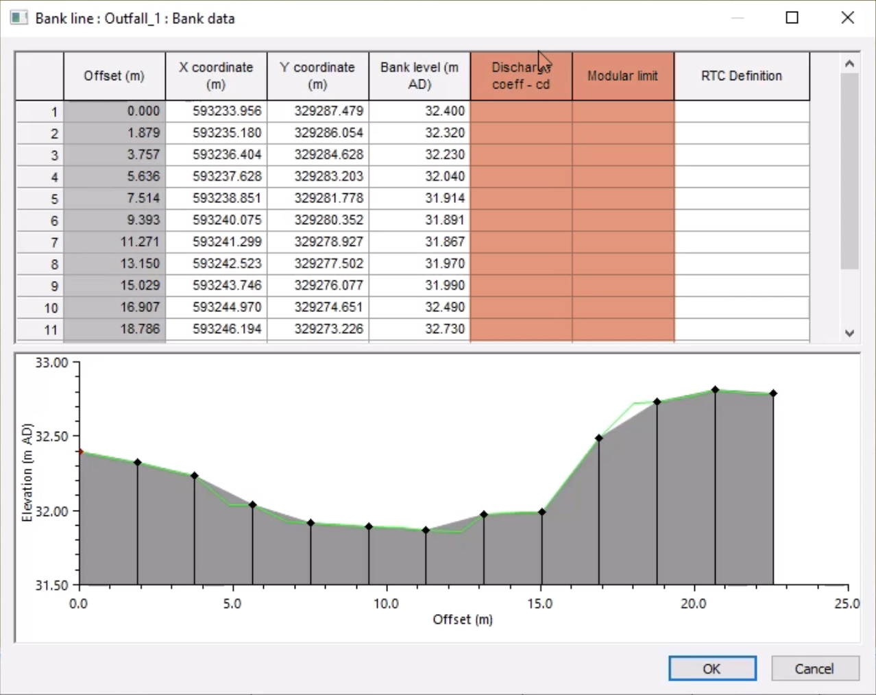
- On the GeoPlan, double-click one of the bank lines to open the Properties window.
- In the Bank data field, click the More (…) button.
In the Bank data window, notice that the Bank level data now exists, but the discharge coefficient and modular limit fields are blank.
- Select the Discharge coeff – cd column header to select all cells in the column.
- Right-click one of the cells and select Set new value(s) for cell(s).
- In the New Cell Value popup, enter a new value of 1.7.
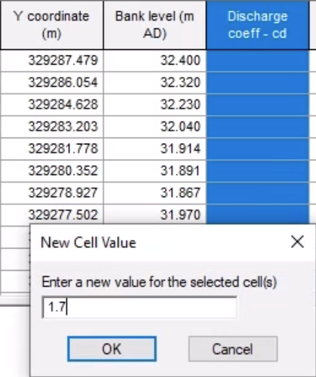
- Click OK.
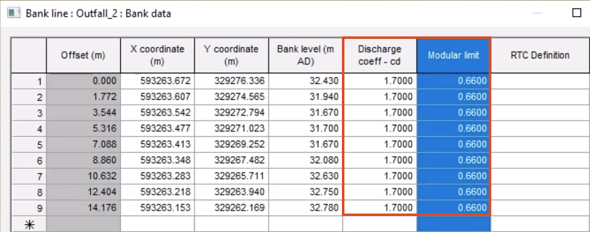
- Repeat steps 51-54 for the Modular limit column, setting a value of 0.66.
- Repeat steps 49-55 for the second bank line.
- Using the Selection tool, on the GeoPlan, drag to select the inline banks and corresponding bank lines.
- From the Model menu, select Inline bank > Build section data from selected bank line.
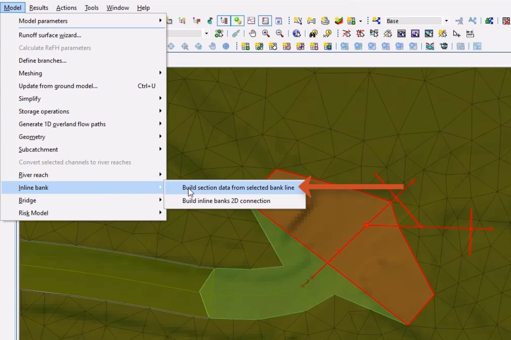
Note: The process is complete when the inline bank creates a dotted line over the bank line.
With bank lines imported and inline banks created and populated with the bank line geometry, the next step is to build their connection to the inline banks.