Associate hydrants and valves to pipelines
Any referenced datasets can be downloaded from "Module downloads" in the module overview.
When working on a calibrated hydraulic model in InfoWater Pro UDF, there are a couple of methods available for associating hydrants and valves with pipes:
- Choose to have InfoWater Pro do it automatically
- Assign pipe IDs manually
Note that when existing InfoWater junctions are used as hydrants or valves, no association is necessary. Then, hydrants are connected to the system via laterals that are InfoWater pipes, and pipes are already broken at the location of valves or junctions.
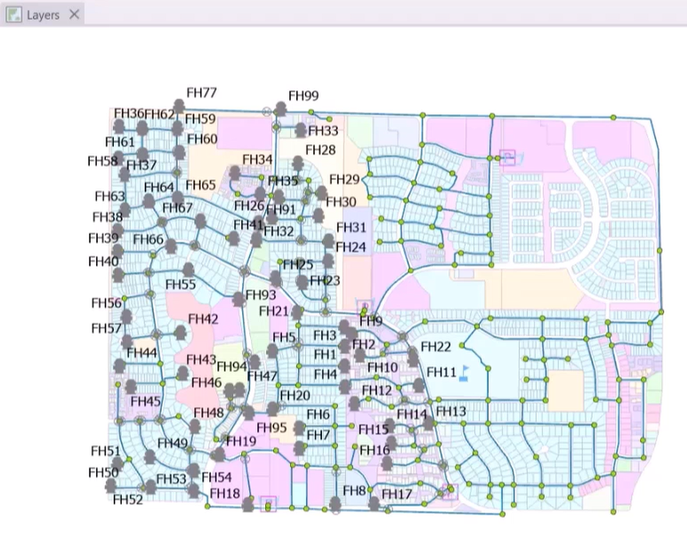
- Open a calibrated hydraulic model with hydrant and valve layers already added in the map.
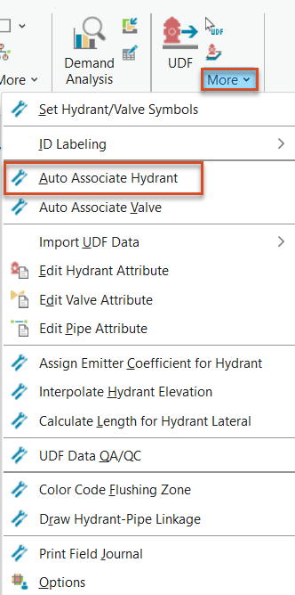
When hydrants are imported from an external node layer, laterals are not imported. To associate the hydrants automatically:
- From the InfoWater Pro ribbon, UDF panel, expand the More drop-down and select Auto Associate Hydrant.
- In the Auto Associate Hydrants dialog box, specify a maximum Searching Distance to the nearest pipe—for this example, 200 (with feet as the active unit in InfoWater Pro).
- Click Auto Associate Pipe.
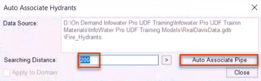
- In the confirmation popup, click OK.
- When the auto association process is done, click Close.
To view laterals between hydrants and associated pipes as red lines:
- From the InfoWater Pro ribbon, UDF panel, expand the More drop-down and select Draw Hydrant-Pipe Linkage.
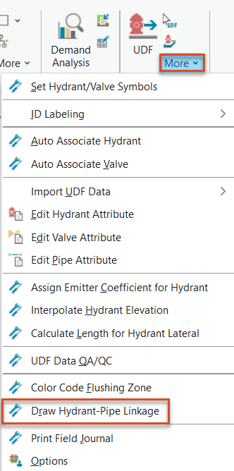
These are for visualization only and do not impact a UDF simulation.
When an external valve layer is imported, valves float over, but do not break the underlying pipe. To associate valves automatically:
- From the InfoWater Pro ribbon, UDF panel, expand the More drop-down and select Auto Associate Valve.
- Click Auto Associate Hydrant.
- Click OK to close the confirmation popup.
- Click Close.
UDF associates valves with the underlying pipe, and the pipe is segmented, or broken, only during UDF simulations.
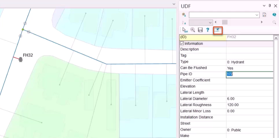
Hydrants or valves with pipes can also be associated manually—for example, to fix auto-association errors. To change the pipe that is linked to a hydrant:
- From the Model Explorer, select the UDF tab.
- In the Attribute toolbar, enable the UDF Select tool.
- Pick the hydrant in the map.
- Click Assign Pipe ID.
- On the map, select the pipe to associate the hydrant with.
The new Pipe ID appears in the hydrant attribute table.
To update the map with the link to the new pipe:
- From the InfoWater Pro ribbon, UDF panel, expand the More drop-down and select Draw Hydrant-Pipe Linkage.
Like hydrants, pipe IDs can be manually assigned to valves with the Assign Pipe ID tool.