When working in InfoWater Pro UDF, emitter (or nozzle) coefficients can be assigned to fire hydrants in a hydraulic model. The emitter coefficient represents the flow—in flow units—that occurs at a pressure drop of 1 psi (or meter).
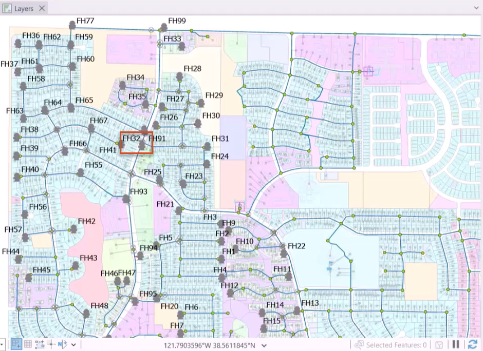
- Open a hydraulic model with hydrant and valve layers already added in the map
- Select one of the hydrants.
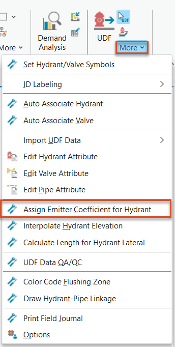
- From the InfoWater Pro ribbon, UDF panel, expand the More drop-down and select Assign Emitter Coefficient for Hydrant.
The Specify Emitter Coefficient for Hydrant dialog box opens.
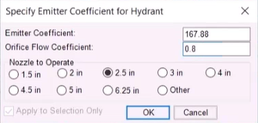
- Emitter Coefficient - Automatically populated based on the specified orifice coefficient and the nozzle size, unless Other is selected in the Nozzle to Operate group box. When Other is selected, any coefficient can be entered here and assigned to the specified hydrants.
- Orifice Flow Coefficient – Enter the desired value, which must be between 0.5 and 1.0. This value is used in conjunction with the nozzle size to calculate the emitter coefficient.
- Nozzle to Operate group box – Select the nozzle size to be used to flush the corresponding hydrant. To set user-defined coefficients, choose Other.
- Apply to Selection Only – When selected, the emitter coefficient is assigned only to selected hydrants. If unselected or grayed out, the coefficient is assigned to all hydrants in the hydrant feature class.
For this example, assign the following settings for hydrant FH32:
- Set an Emitter Coefficient of 167.88.
- Set an Orifice Flow Coefficient of 0.8.
- Set a Nozzle to Operate size of 2.5 inches.
- Click OK to save changes and close the dialog box.
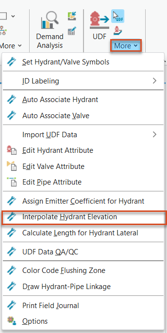
If elevation data was not imported into the model, elevations can be assigned to hydrants manually:
- From the InfoWater Pro ribbon, UDF panel, expand the More drop-down and select Interpolate Hydrant Elevation.
- For this example, select Update Elevation to UDF Database.
- Click Interpolate.
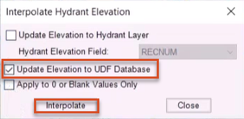
- In the confirmation popup, click OK.
- Close the Interpolate Hydrant Elevation dialog box.
Before reviewing the emitter coefficients and elevation data for the hydrants in the map, the length of hydrant lateral connections can also be calculated:
- From the InfoWater Pro ribbon, UDF panel, expand the More drop-down and select Calculate Length for Hydrant Lateral.
- Click OK to close the popup.
- Expand the More drop-down again, and click Edit Hydrant Attribute.
- In the Hydrant Attributes dialog box, review the ID, emitter coefficient, elevation, lateral length, and other values associated with each hydrant.
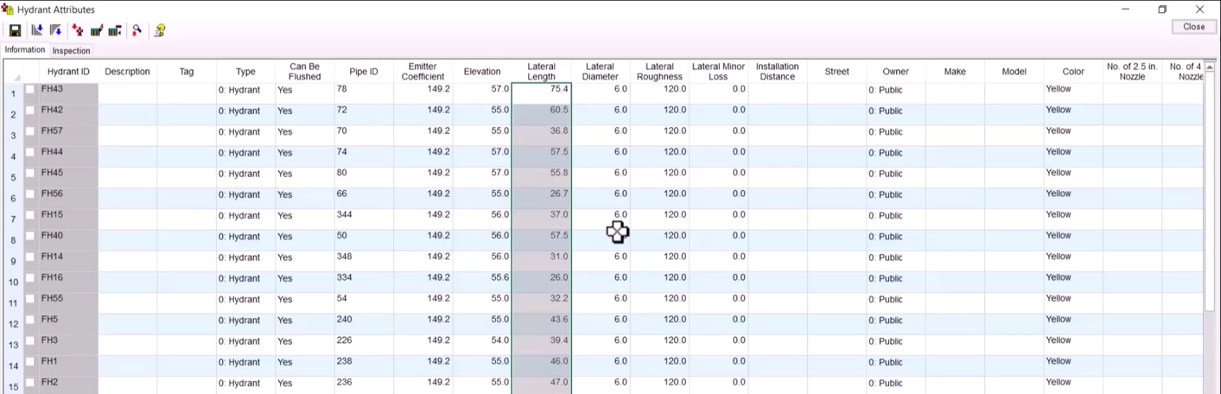
- Click Close.


