Create a calibrated hydraulic model and set the UDF layers
Any referenced datasets can be downloaded from "Module downloads" in the module overview.
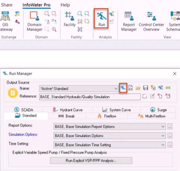
Before running a UDF simulation in InfoWater Pro, you must first have a working hydraulic model calibrated to reflect real-world operations.
To ensure that the model works:
- Run a standard hydraulic simulation and confirm that the model has run successfully.
This ensures that changes in demand, flow, and velocity are considered during a UDF simulation.
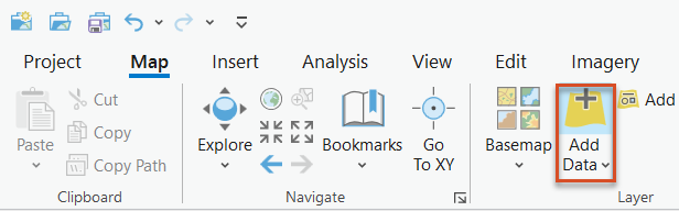
With a working model open, first, add the hydrant and valve layers to the map:
- From the ArcGIS Map ribbon, Layer panel, click Add Data.
- In the Add Data dialog box, navigate to and select the hydrant and valve layer files to use.
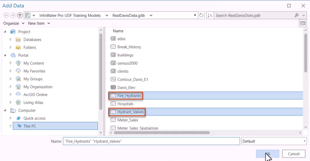
- Click OK.
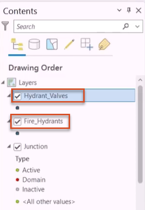
The layers now appear in the Contents pane.
Selection sets of junctions in the model that represent hydrants and valves can also be created and used for hydrant and valve definitions.
After adding the hydrant and valve layers, they need to be registered with the UDF interface before flush zones or flush sequences are created.
To set a UDF layer:
- From the InfoWater Pro ribbon, UDF panel, click Set Layer.
The Set UDF Layer dialog box opens and consists of two group boxes, one for the hydrant layer and one for the valve layer. Note that the hydrant and valve layers are ArcGIS layers, which can be updated, modified, and edited using any ESRI functions.
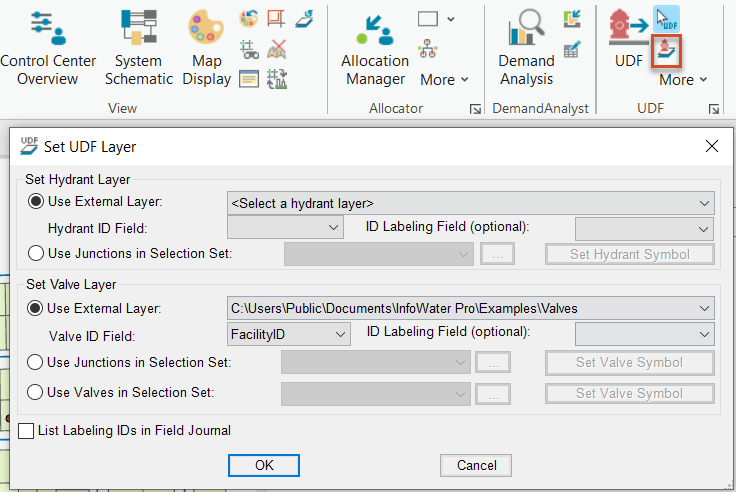
To use a non-InfoWater Pro layer to represent hydrants:
- In the Set Hydrant Layer group box, enable Use External Layer.
- Use the associated drop-down to select the shapefile or feature class that represents hydrants in the system.
Note that the dataset must be contained in the ArcGIS table of contents to appear in this drop-down.
- Expand the Hydrant ID Field drop-down to browse the unique IDs for each hydrant in the selected dataset.
- Use the optional ID Labeling Field drop-down to automatically label all hydrants and valves, or to clear their ID labels from the map display.
Alternatively, use InfoWater Pro junctions in a selection set to represent hydrants:
- Under Set Hydrant Layer, enable Use Junctions in Selection Set.
- Use the associated drop-down to pick a selection set that contains the junctions representing hydrants.
- Click the Ellipsis (…) to access the Selection Set Editor, with options to create, modify, and merge selection sets.
- Pick Set Hydrant Symbol to change the symbology of the InfoWater Pro junctions in the specified selection set from a junction to a hydrant.
- Use the optional ID Labeling Field drop-down to select a field other than the ID field to label on the map.
Note that hydrants must be connected via laterals, as mainline nodes cannot be hydrants.
The functions in the Set Valve Layer group box work the same way, except for the Use Valves in Selection Set option, which uses InfoWater Pro hydraulic valves in a selection set to represent UDF valves.
- Once the layers are set, click OK.
To set hydrant and valve symbols on the map:
- From the UDF panel, expand the More drop-down and select Set Hydrant/Valve Symbols.
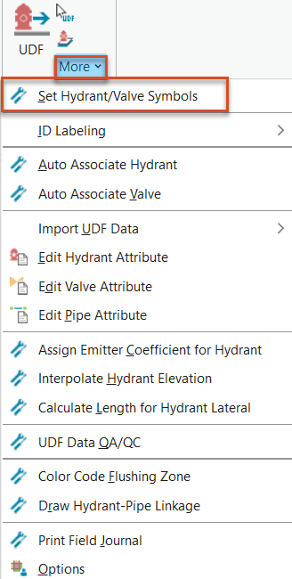
Note that the updated symbols appear in the Contents pane under the hydrant and valve layers, and on each hydrant and valve in the map.
To place ID labels on hydrants and valves:
- From the UDF panel, select More > ID Labeling, and then select Hydrant or Valve.
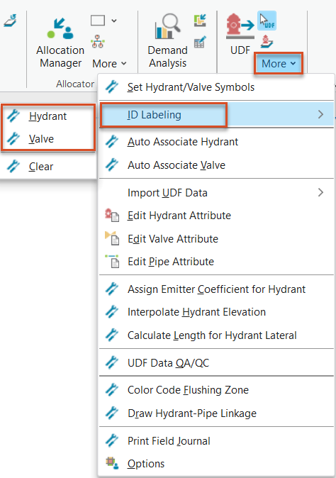
- In the same menu, click Clear to remove ID labels.