Setting up references
Any referenced datasets can be downloaded from "Module downloads" in the module overview.
Setting up references - Exercise
Task 1: Copy/monitor architect's levels
- Open the project STRUCTURAL (after Initial Setup).rvt.
- Open the South elevation view.
- Use Visibility/Graphics Overrides dialog to hide the Planting and Entourage Model Categories.
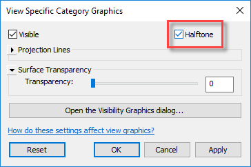
- Select the link, right-click, and select Override Graphics in View > By Category.
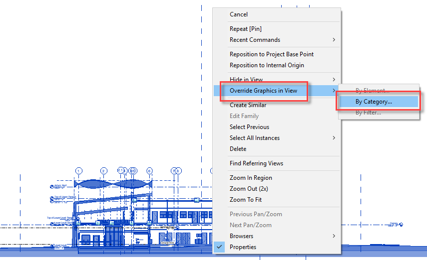
- In the View Specific Category Graphics dialog, enable the Halftone option.
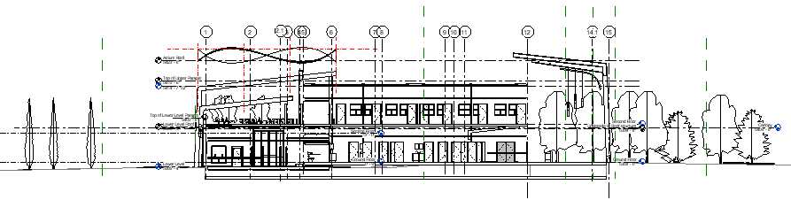
- You can now differentiate more easily the levels already in the project with the architectural link faded out in the background. Grip edit the Ground Floor and Second Floor level lines to extend either side of the building.
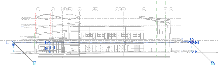
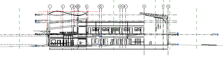
- Zoom into the right-hand side of the elevation.
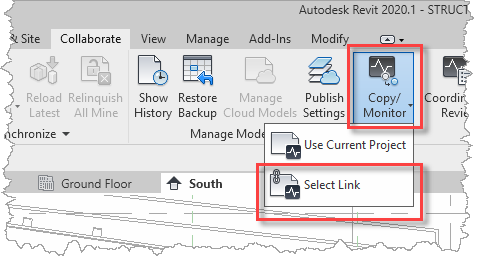
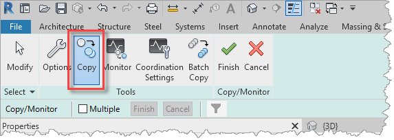
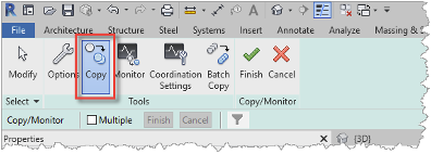
- From the Collaborate ribbon, select Copy/Monitor, then Select Link.
- Select the link in the elevation view, then select Copy in the Copy/Monitor ribbon.
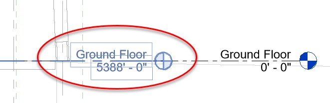
- Select the Ground Floor level in the link file.
- Next, select the Second Floor level in the link file.
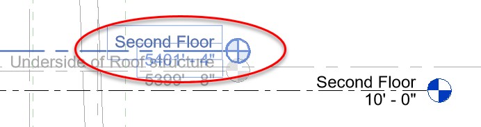
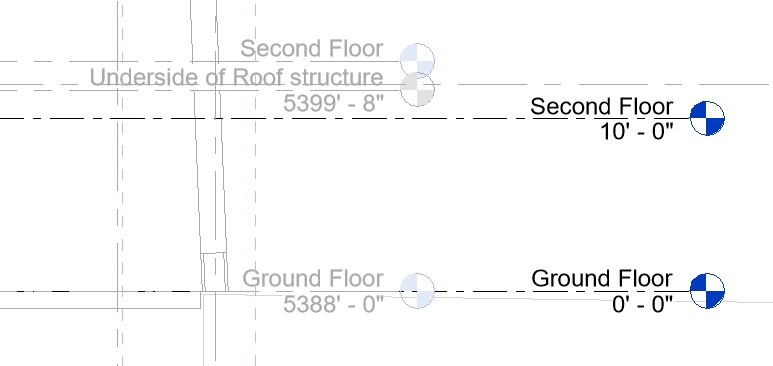
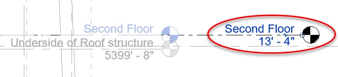
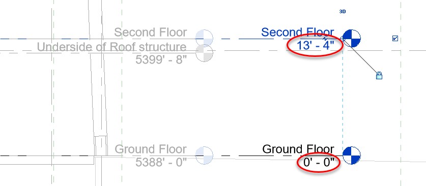
- In this case, the Second Floor level in the host project is being matched by name to the one in the link, and then has its elevation updated from 10' – 0" to 13' – 4".
- Finally, pan to the top left corner of the elevation and copy the Atrium Roof level.

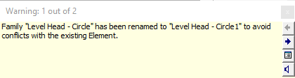
- Take note of the warning that: Family "Level Head - Circle" has been renamed to "Level Head - Circle1" to avoid conflicts with the existing Element, as shown below.
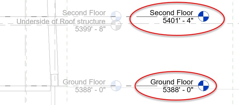
- Also take note that the elevation on our new level lines, reporting an elevation relative to the Survey Point (for example, Second Floor now displays 5401' - 4" rather than 31' - 4").
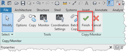
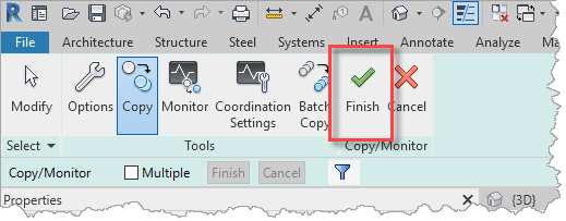
- To revert back to display elevations relative to the building's Ground Floor level, first exit the Copy/Monitor process. Select Finish from the Copy/Monitor ribbon.
- Select one of the level lines, then select Edit Type from the Properties palette.
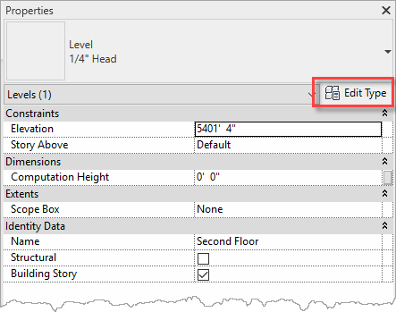
- In the Type Properties dialog, change the Elevation Base from Survey Point to Project Base Point.
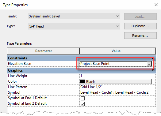
- Note that the levels in the host project are now displaying elevations relative to the Project Base Point.
Task 2: Create new structural levels
- Still in the South view, add two new level lines below the Ground Floor level (the Level tool is located on the Architecture ribbon – Datum panel).
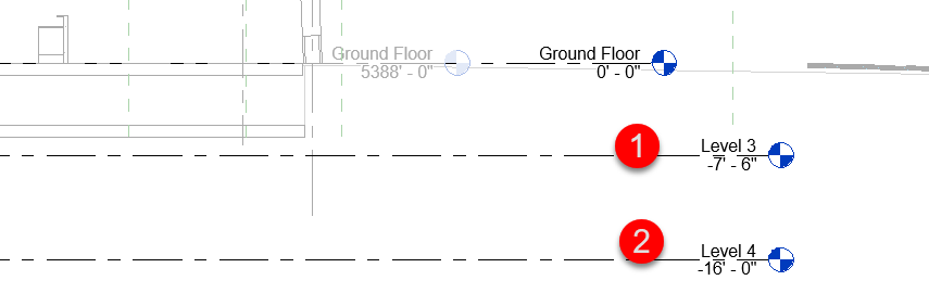
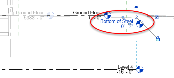
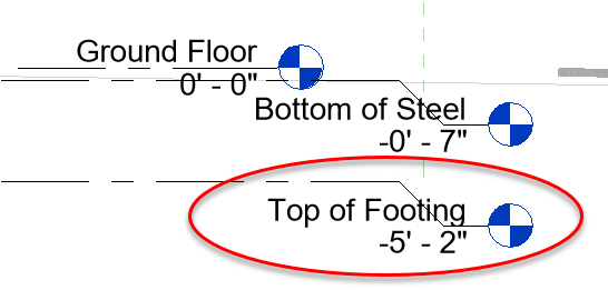
- Name the first level Bottom of Steel, set its elevation to -0' 7", and use the Add elbow grip to add a dogleg so that the level's annotation does not clash with the Ground Floor level.
- Name the second level Top of Footing and set its elevation to -5' 2" (that might also require a dogleg added).
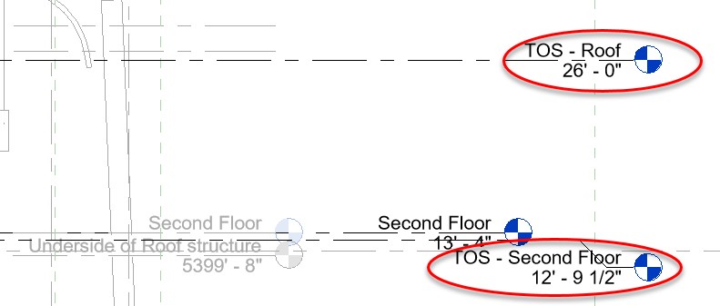
- Repeat this process to add two more levels: TOS – Second Floor at 12' 9 ½" and "TOS – Roof" at 26' 0".
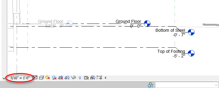
- At this view scale (1/8"= 1'-0") the level annotations are still overlapping. You can reduce the size of the text by changing the view scale, for example 3/16"=1'-0".
Task 3: Copy/monitor architect's grids
- Open the Ground Floor structural plan.
- From the Collaborate ribbon, select Copy/Monitor, then Select Link.
- Select the link in the plan view, then select Copy in the Copy/Monitor ribbon.
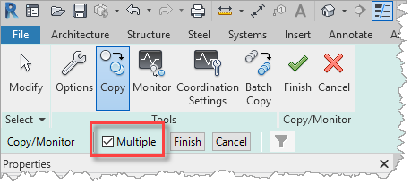
- Enable the Multiple option on the Options Bar.
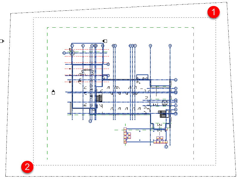
- Then, window-select around the entire building footprint in the Ground Floor plan.
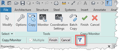
- Select the Filter button on the Option Bar.
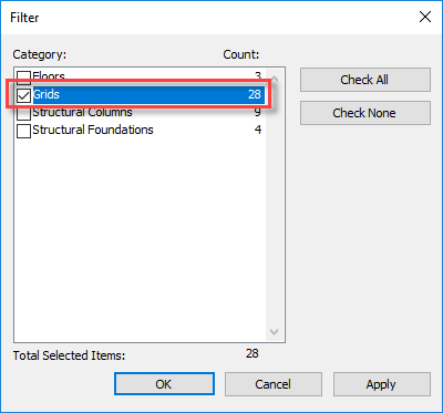
- Uncheck all categories in the list except Grids.
- Select the Finish button on the Option Bar.
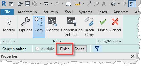
- Hit Escape to deselect the grids, to close the Modify | Grids ribbon, and then select Finish from the Copy/Monitor ribbon.