Setting up views
Any referenced datasets can be downloaded from "Module downloads" in the module overview.
Setting up views - Exercise
Task 1: Adding new plan views
This task will check for missing structural plans and step through the process of creating a new structural plan.
- Open the project STRUCTURAL (after Setting up References).rvt.
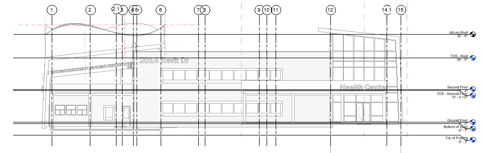
- Open the South elevation view.
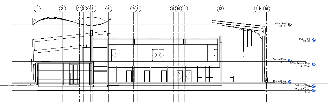
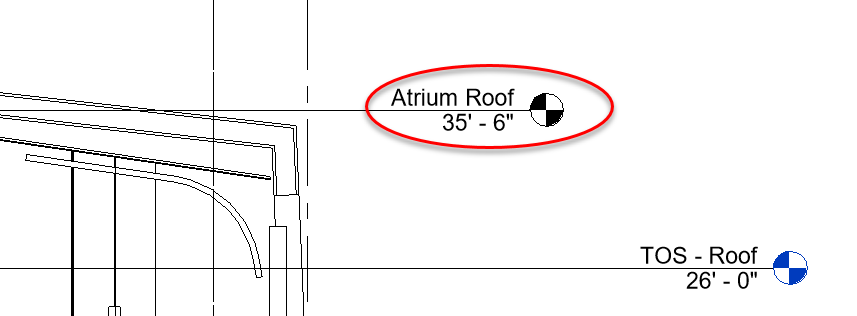
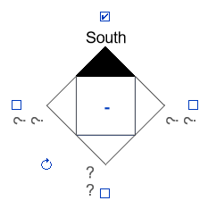
- Zoom over to the level heads and take note that Atrium Roof header bubble is black whereas TOS – Roof is blue. This implies that there is no plan view associated with the Atrium Roof level.
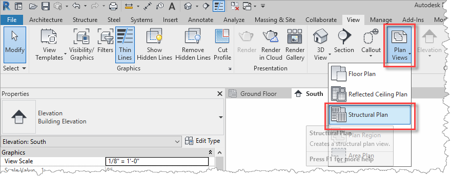
- From the View ribbon, select Plan Views, then select Structural Plan.
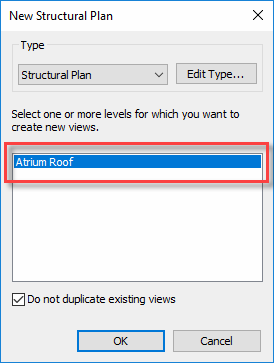
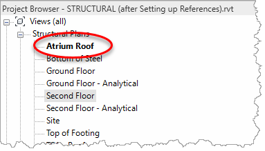
- In the New Structural Plan dialog, select Atrium Roof and OK the dialog.
- The new Atrium Roof view is added to the Project Browser as a new Structural Plan.
Task 2: Update elevation views
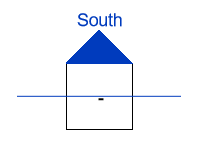
This task will adjust the elevation views so that they are displaying the exterior of the architectural model rather than cutting through like a section. This issue has been caused by the misalignment between the architect’s model and the elevation markers placed in the structural model template (as illustrated below).
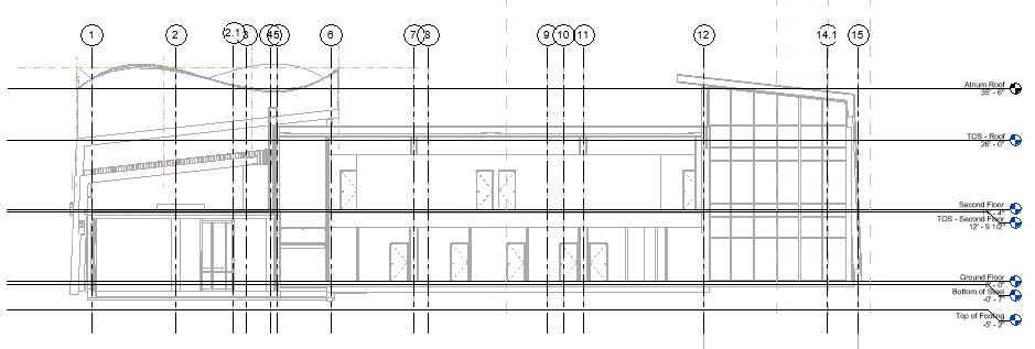
- The issue with the elevations can be demonstrated if you switch to the South elevation, although not necessarily totally apparent, this view is cutting through the building like a section rather than an external elevation.
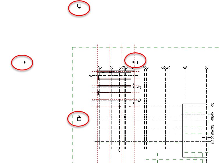
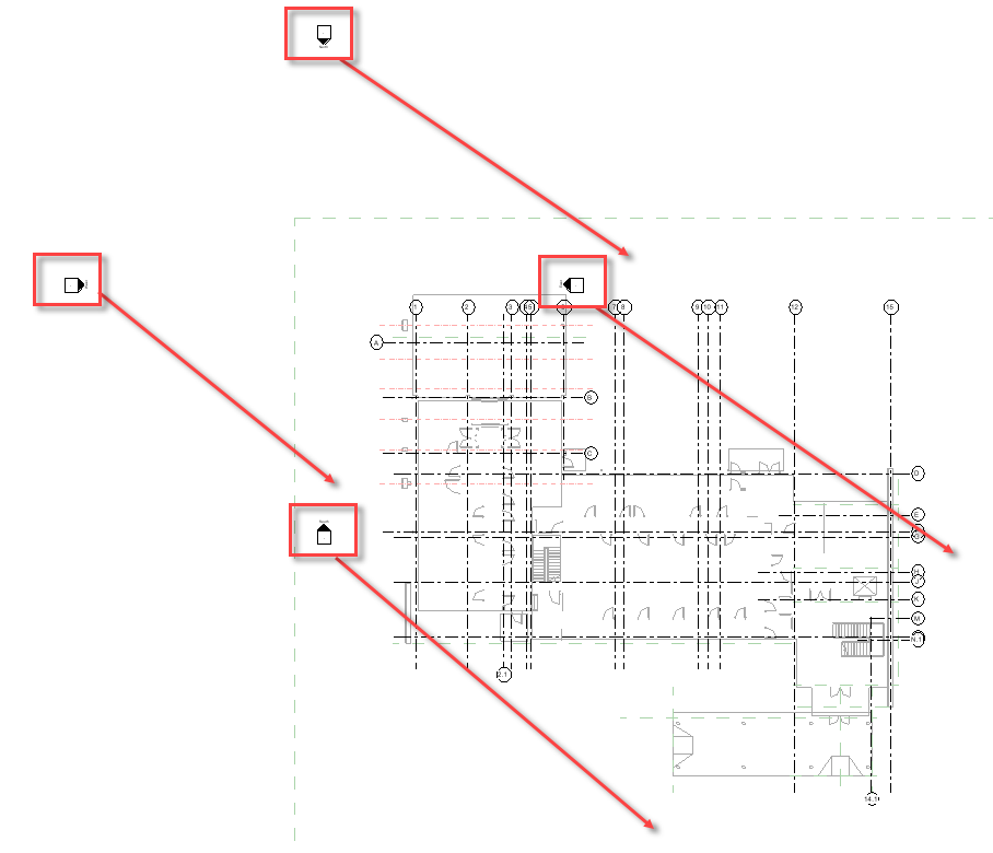
- Switch back to the plan view and review the elevation markers. On closer inspection, each marker consists of two objects: a View object and an Elevation object.
- When moving the markers, take care to move both objects together by windowing around both.
- Move each pair to exterior of the building footprint.
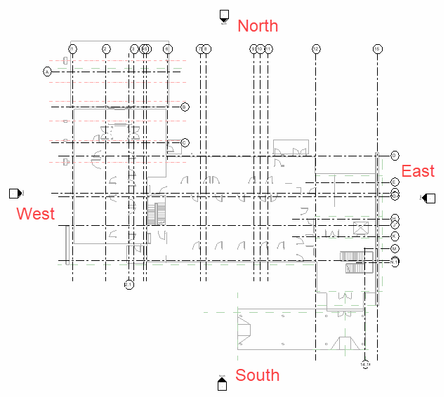
- The plan should now look something like the image below.
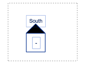
- And the South view should look something like the image below.
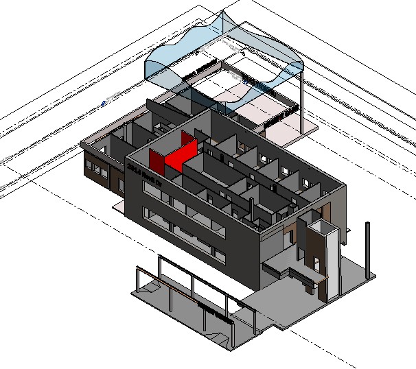
Task 3: Create 3D coordination view
This task will go through the process of setting up a 3D coordination view of the model so that the structural model can be viewed together with the architectural and MEP models.
- Open the default {3D} view and switch to Shaded display, and you see the current architect's model, but it seems there is a lot of detail missing.
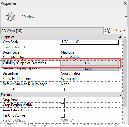
- From the view's Properties palette, select Edit for Visibility/Graphics Overrides.
- In the Visibility/Graphic Overrides dialog, switch to the Model Categories tab, ensure that Filter List is set to <show all> (by checking each of the disciplines in the droplist), then select the All button.
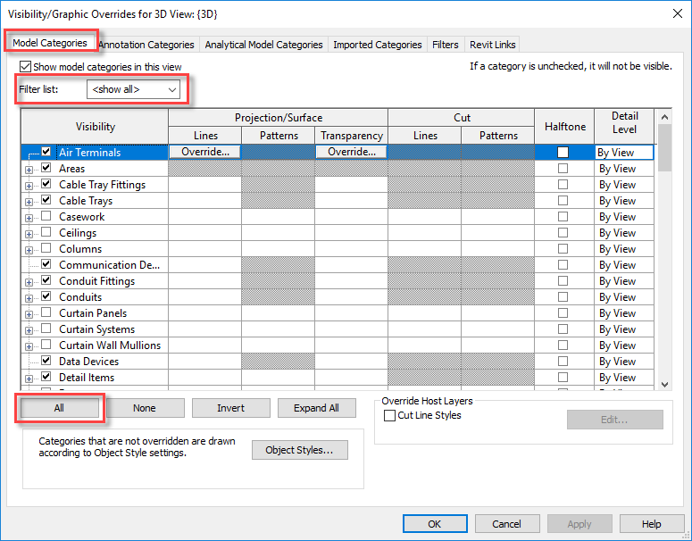
- With all the Model Categories selected, enable one of the unchecked categories (e.g. Columns in the example above) and all Model Categories will be checked.
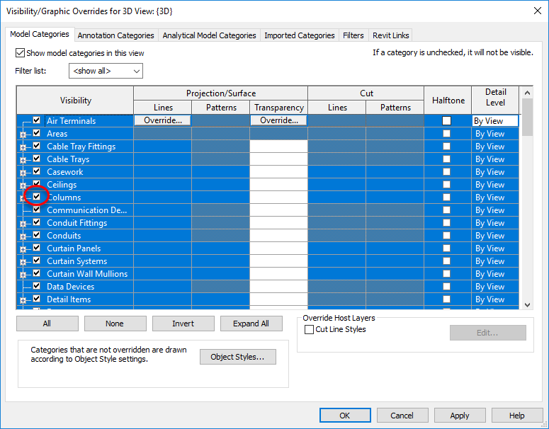
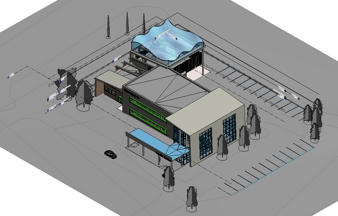
- Click OK in the dialog to close it and now the 3D view is displaying a lot more.
- There is now more detail than needed, for example we are only interested in the building objects, so next turn off some of the non-building objects. Back in the Visibility/Graphic Overrides dialog (through the view's properties or simply type VG), uncheck Entourage, Parking, Planting, Site, and Topography.
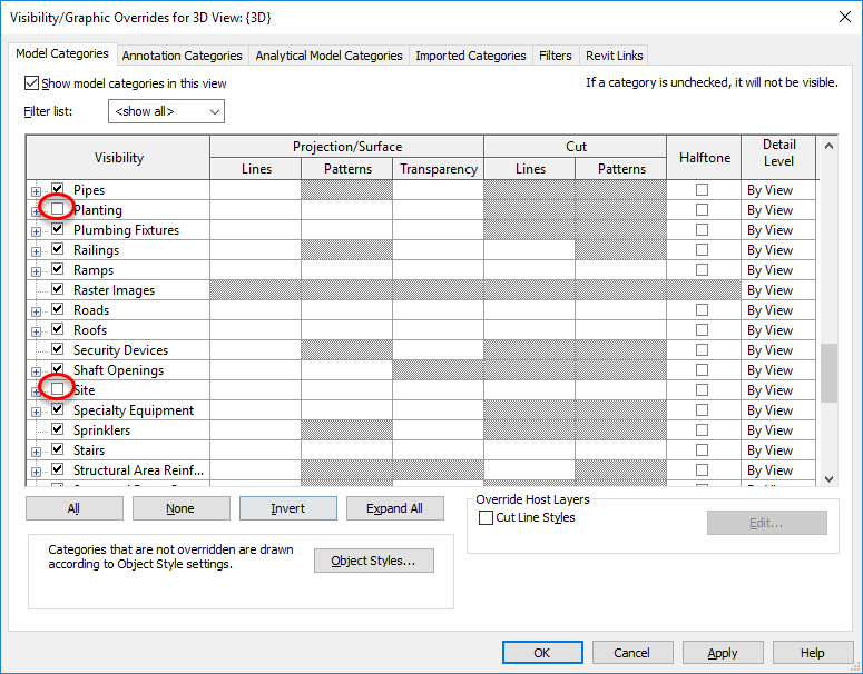
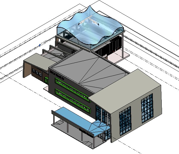
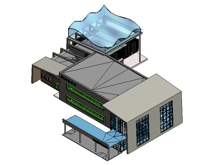
- Click OK in the dialog to close it and now the 3D view is displaying just the building without the site.
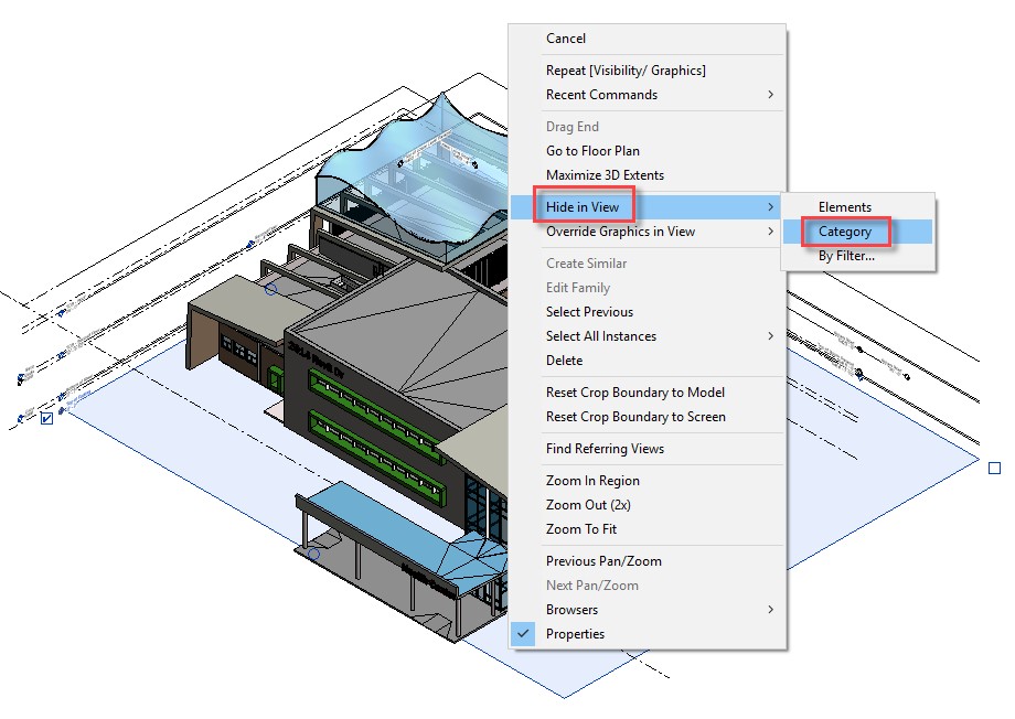
- The level lines are a bit distracting in this 3D View, so select one of them, right-click, and select Hide in View, then Category.
- The view should now look something like this.
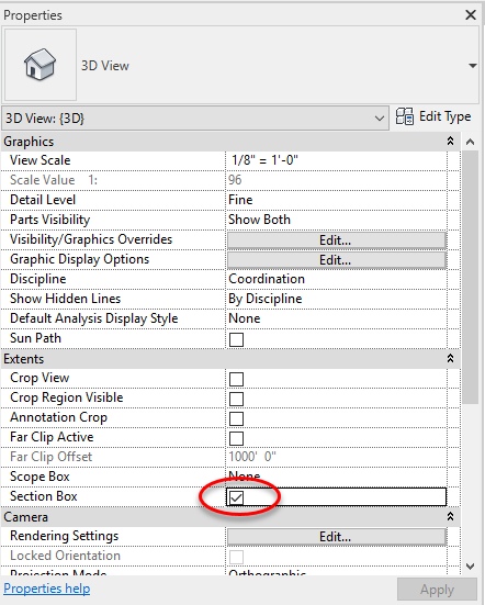
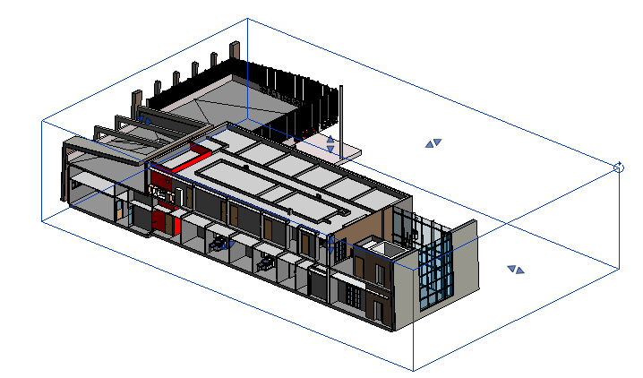
- To understand the construction of the building, we shall "slice & dice" it, using a section box. In the view's properties, enable Section Box.
- Use the grips on the Section Box and drag them so that the building model is cut open.
- To further explore the model, set objects such as ceilings, floors, roofs, and walls to transparent. To do this, open the Visibility/Graphic Overrides dialog, select Ceilings, then select the Override option for Projection/Surface Transparency.
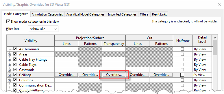
- In the Surfaces dialog, set Transparency to 70 (this is a percentage with 0% being opaque and 100% being totally transparent).
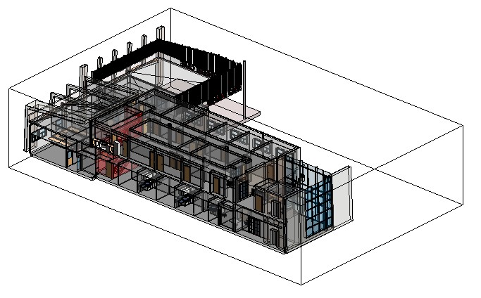
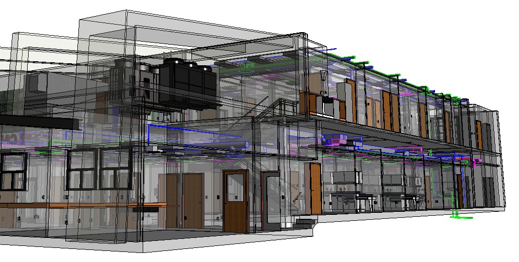
- Repeat this for Floors, Roofs, and Walls, then OK the dialog and the view should look something like this and it is now possible to see through the building.
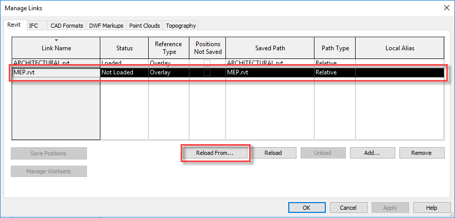
- In a previous exercise, the MEP model had been linked into this project but then unloading. To redisplay the MEP model, select Manage Links from the Insert ribbon.
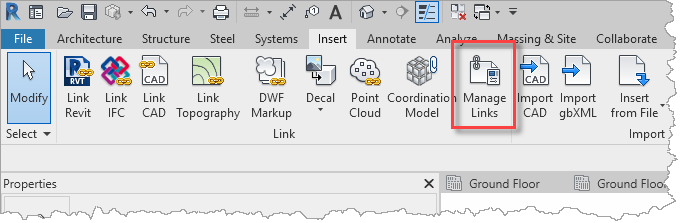
- In the Manage Links dialog, select MEP.rvt, then select Reload From and navigate to where the MEP.rvt file is saved locally.
- Zooming in, the model displays the mechanical services in context with the building.
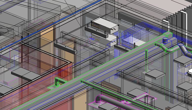
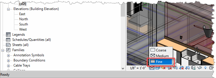
- If the view is set to a Medium or Course Detail Level, set the Detail Level to Fine.
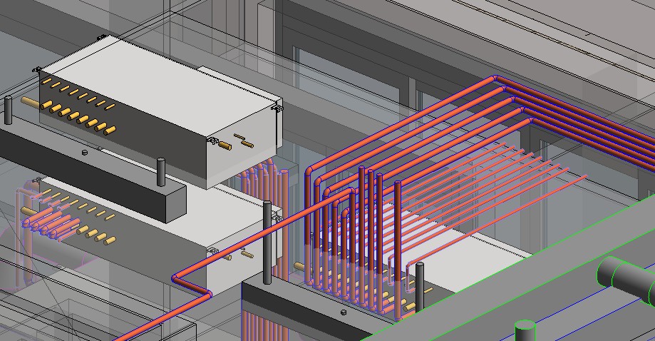
- Pipes that were previously displayed as a single centre line will now display in full 3D to provide greater clarity for coordination with the structural model.
- Try out the different Visual Styles (e.g. Realistic with Edges), hide the Section Box, and you can start exploring the model, to determine what is required for the structure.

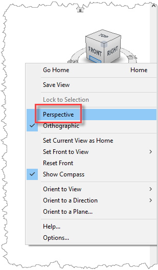
- For additional clarity, right-click on the View Cube and select Perspective.
- Use the Orbit tool to view the model from various angles.
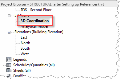
- For clarity, it would be a good idea to rename this view from {3D} to 3D Coordination in the Project Browser.
Our project is now ready to start developing the structural model in coordination with the current architectural and mechanical services designs.