• Revit
  • Navisworks Products

Use coordination models

Insert a coordination model from Navisworks into Revit, adjust the display of the coordination model, and manage the links of the coordination model. 


00:03

You can insert a coordination model from Navisworks into Revit

00:07

to coordinate your design with the work of teams who use different software.

00:11

Coordination models are lightweight files that provide context for your Revit model,

00:16

and allow you to crosscheck various disciplines with your design.

00:20

To insert a coordination model, begin with Revit open.

00:24

From the ribbon, Insert tab, click Link.

00:29

Expand Coordination Model and then choose the source of your model, either Local or Autodesk Docs.

00:36

Then, from the file browser, select the appropriate .nwd or .nwc file.

00:43

Click Open to insert the coordination model into your model.

00:47

The coordination model displays in the current view, surrounded by a bounding box.

00:53

In Revit, a coordination model is a single model element, so it will display in all views, not just the current view.

01:00

Pin the coordination model in place, so it is not accidentally repositioned while you work.

01:06

With the coordination model selected, from the ribbon, Modify | Coordination Model tab, expand the Modify panel.

01:15

Then, select Pin.

01:18

To control the display of coordination models, use the visibility and graphics dialog.

01:25

From the ribbon, View tab, expand the Graphics panel.

01:29

Then, select Visibility/Graphics.

01:33

In the dialog, open the Coordination Models tab.

01:37

Under Visibility, select the model you wish to adjust,

01:42

and then in the adjacent cell of the Projection/Surface and Transparency column, select Override.

01:48

In this example, the transparency is adjusted in the Surfaces dialog using the slider.

01:54

Click OK.

01:57

Back in the Visibility/Graphics dialog, click Apply to commit the changes.

02:02

Click OK.

02:04

You can also create multiple instances of a coordination model to add context to your design.

02:11

Open the Modify tab again, and then expand the Coordination panel.

02:16

Select Manage Links.

02:19

In the Manage Links dialog, Coordination Model tab, select the model from which you wish to create another instance.

02:27

Then, expand Place Instance and select a placement option:

02:31

Choosing Origin to Internal Origin aligns the origin of the coordination model with the internal origin of the Revit model.

02:39

Selecting Shared Coordinates aligns the models based on shared coordinates.

02:44

When using a coordination model as a reference, you can manage the link in this dialog as well.

02:50

You can reload, unload, or remove links from the model as needed.

02:55

When you are ready, click OK.

02:58

By loading the updated coordination model regularly, such as weekly, you minimize the risk of clashes.

03:05

This practice can expedite the design process and reduce the need to make changes, saving time and money for the entire design team.

Video transcript

00:03

You can insert a coordination model from Navisworks into Revit

00:07

to coordinate your design with the work of teams who use different software.

00:11

Coordination models are lightweight files that provide context for your Revit model,

00:16

and allow you to crosscheck various disciplines with your design.

00:20

To insert a coordination model, begin with Revit open.

00:24

From the ribbon, Insert tab, click Link.

00:29

Expand Coordination Model and then choose the source of your model, either Local or Autodesk Docs.

00:36

Then, from the file browser, select the appropriate .nwd or .nwc file.

00:43

Click Open to insert the coordination model into your model.

00:47

The coordination model displays in the current view, surrounded by a bounding box.

00:53

In Revit, a coordination model is a single model element, so it will display in all views, not just the current view.

01:00

Pin the coordination model in place, so it is not accidentally repositioned while you work.

01:06

With the coordination model selected, from the ribbon, Modify | Coordination Model tab, expand the Modify panel.

01:15

Then, select Pin.

01:18

To control the display of coordination models, use the visibility and graphics dialog.

01:25

From the ribbon, View tab, expand the Graphics panel.

01:29

Then, select Visibility/Graphics.

01:33

In the dialog, open the Coordination Models tab.

01:37

Under Visibility, select the model you wish to adjust,

01:42

and then in the adjacent cell of the Projection/Surface and Transparency column, select Override.

01:48

In this example, the transparency is adjusted in the Surfaces dialog using the slider.

01:54

Click OK.

01:57

Back in the Visibility/Graphics dialog, click Apply to commit the changes.

02:02

Click OK.

02:04

You can also create multiple instances of a coordination model to add context to your design.

02:11

Open the Modify tab again, and then expand the Coordination panel.

02:16

Select Manage Links.

02:19

In the Manage Links dialog, Coordination Model tab, select the model from which you wish to create another instance.

02:27

Then, expand Place Instance and select a placement option:

02:31

Choosing Origin to Internal Origin aligns the origin of the coordination model with the internal origin of the Revit model.

02:39

Selecting Shared Coordinates aligns the models based on shared coordinates.

02:44

When using a coordination model as a reference, you can manage the link in this dialog as well.

02:50

You can reload, unload, or remove links from the model as needed.

02:55

When you are ready, click OK.

02:58

By loading the updated coordination model regularly, such as weekly, you minimize the risk of clashes.

03:05

This practice can expedite the design process and reduce the need to make changes, saving time and money for the entire design team.

Step-by-step guide

A coordination model can be inserted from Navisworks into Revit to coordinate a design with the work of teams who use different software. Coordination models are lightweight files that provide context for the Revit model, as well as allow the cross-checking of various disciplines with the design.

To insert a coordination model:

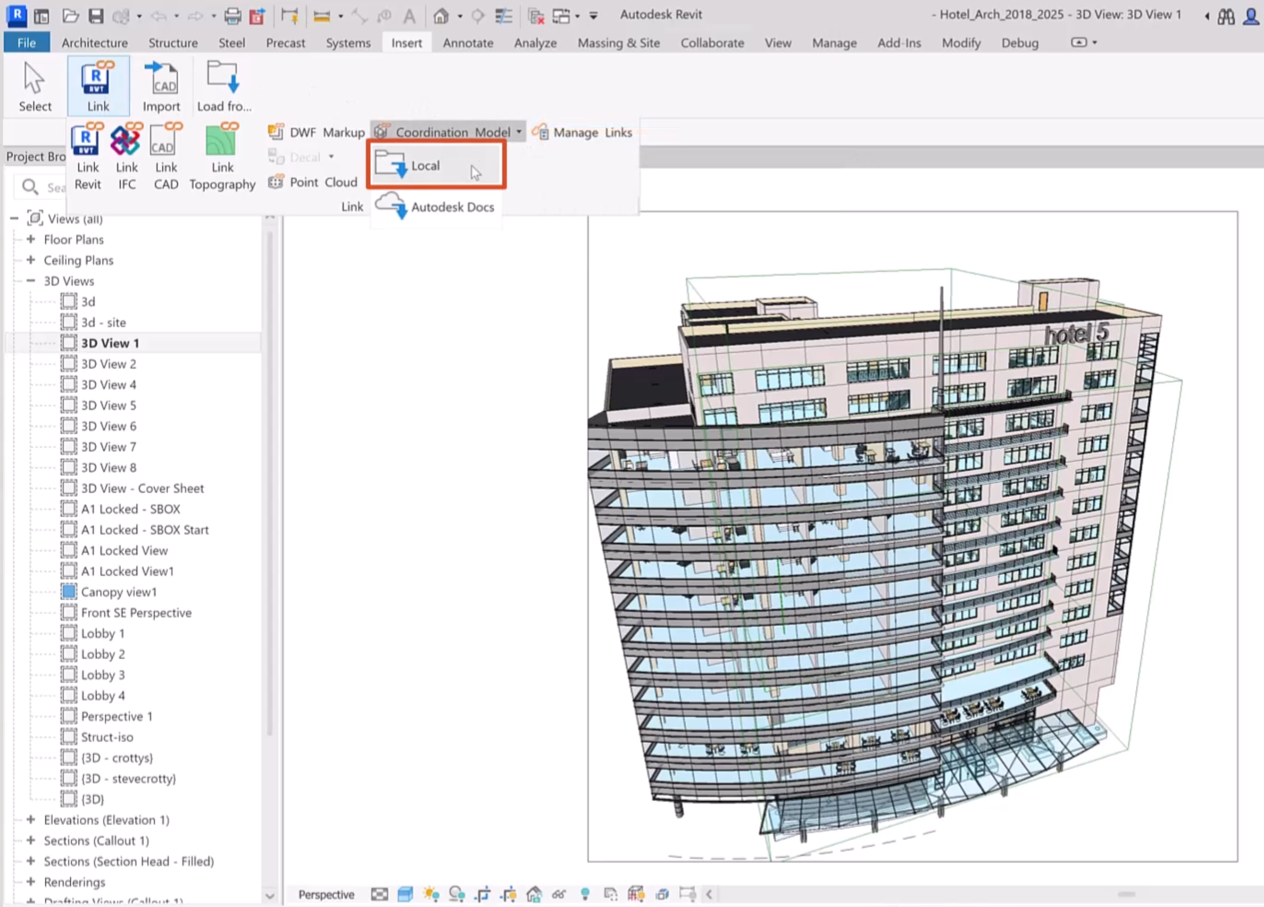
  1. In Revit, on the ribbon, Insert tab, click Link.
  2. Expand Coordination Model and choose the source of the model.

In Revit, a hotel model is open in the drawing area. The Insert ribbon is showing, with the Link panel expanded, and in the Coordination model drop-down, Local selected and highlighted in red.

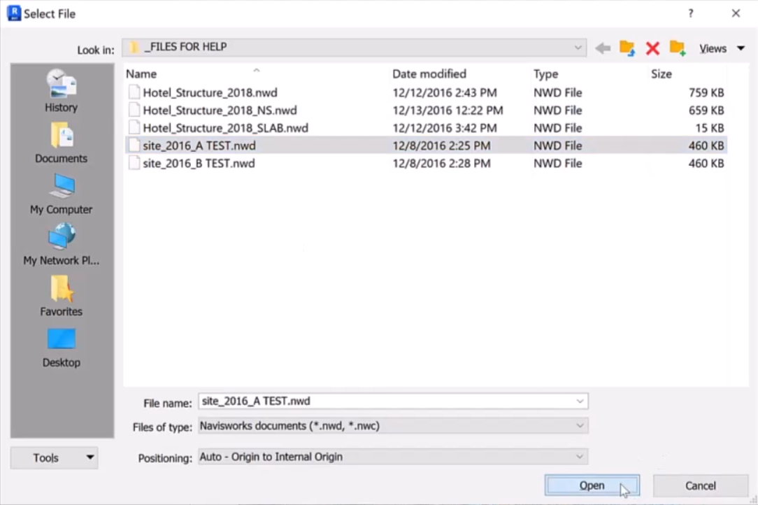
  1. In the Select File dialog box, select the appropriate .nwd or .nwc file.
  2. Click Open.

The Select file dialog box, showing the .nwd file for this example highlighted, with Open selected.

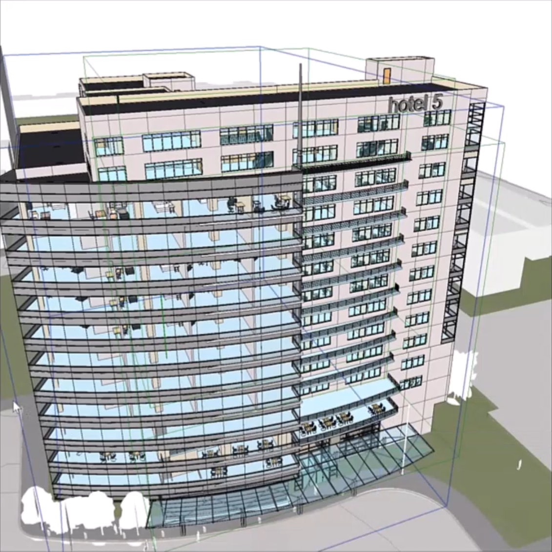
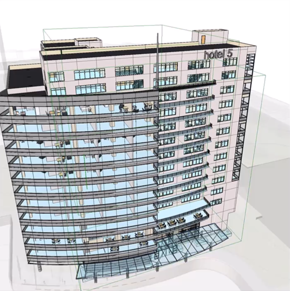
The coordination model displays in the current view, surrounded by a bounding box. In Revit, a coordination model is a single model element, so it displays in all views.

In the view, the coordination model is visible, surrounded by a bounding box.

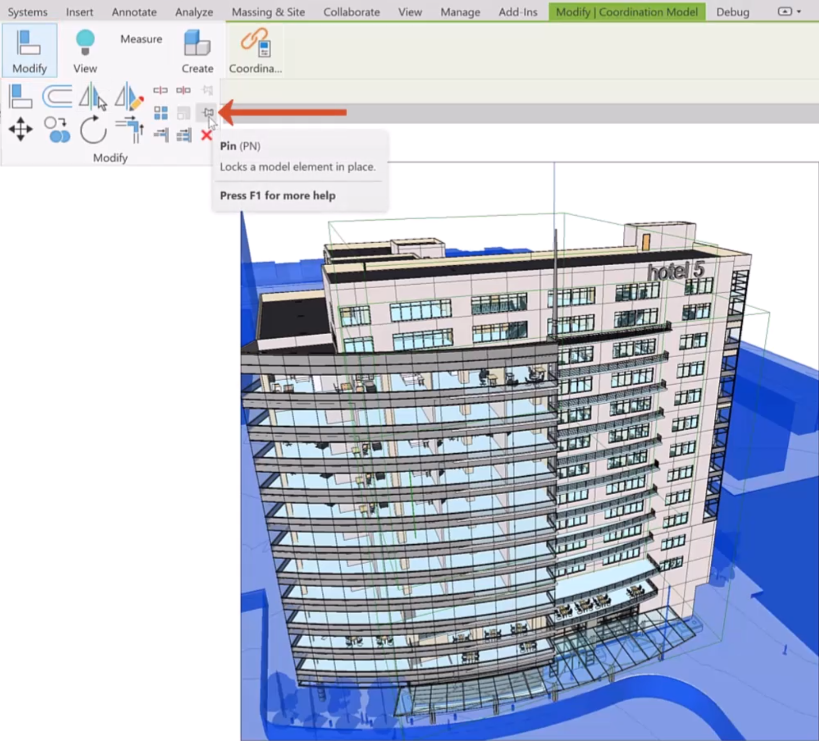
Next, pin the coordination model in place, so it is not accidentally repositioned while working:

  1. With the coordination model selected, from the ribbon, Modify | Coordination Model tab, expand the Modify panel.
  2. Select Pin.

With the coordination model selected in the view, the Modify | Coordination Model contextual ribbon is active and the Modify panel is expanded, with Pin selected and called out.

To control the display of coordination models, use the Visibility and Graphics dialog box:

  1. From the View tab, expand the Graphics panel.
  2. Select Visibility/Graphics.

A portion of the Revit ribbon, showing the View tab, with the Graphics panel expanded and Visibility/Graphics being selected and called out with a red arrow.

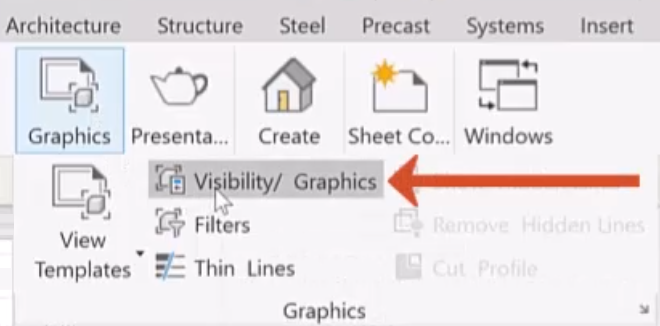
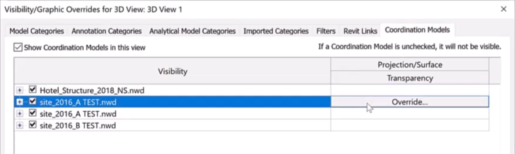
  1. In the dialog box, open the Coordination Models tab.
  2. Under Visibility, select the model you want to adjust.
  3. In the adjacent cell of the Projection/Surface and Transparency column, select Override.

In the Visibility/Graphic Overrides dialog box for the 3D view, the Coordination Models tab is active and a model is selected under Visibility, with Override being clicked in the adjacent cell.

  1. In the Surfaces dialog box, for this example, adjust the Transparency using the slider.
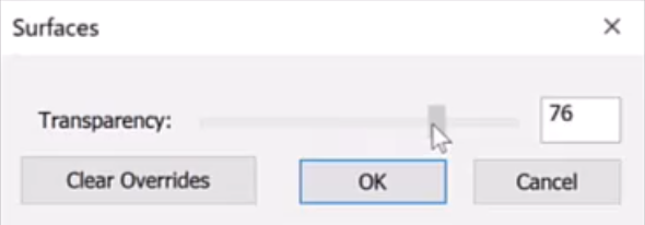
In the Surfaces dialog box, the Transparency slider is being adjusted with the pointer and 76 shows in the Transparency value box.

  1. Click OK.
  2. In the Visibility/Graphics dialog box, click Apply.
  3. Click OK.

The Revit coordination model with the transparency adjusted.

Multiple instances of a coordination model can be created to add context to the design.

  1. On the Modify tab, expand the Coordination panel.
  2. Select Manage Links.
  3. In the Manage Links dialog box, Coordination Model tab, select the model from which to create another instance.
  4. Expand Place Instance and select Origin to Internal Origin to align the origin of the coordination model with the internal origin of the Revit model, or select Shared Coordinates to align the models based on shared coordinates.

The Manage Links dialog box, with the Coordination Model tab active. In the table, a model is selected, highlighted in black. Below the table, the Place Instance drop-down is expanded and highlighted in red.

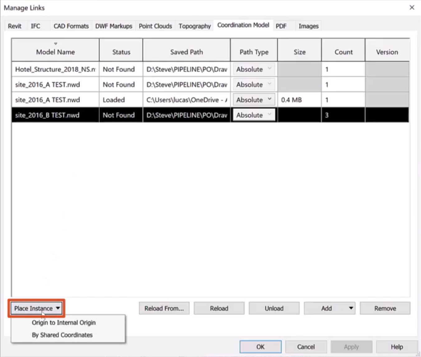
Note the additional options to Reload, Unload, or Remove links from the model as needed.

  1. Click OK.

Loading the updated coordination model regularly, such as weekly, minimizes the risk of clashes. This practice can expedite the design process and reduce the need to make changes, saving time and money for the entire design team.


Was this information helpful?