Creating a 2D base linear structure
Create a 2D Base Linear Structure within a 2D mesh to act as a dam.
Tutorial resources
These downloadable resources will be used to complete this tutorial:
Step-by-step guide
In ICM, 2D base linear structures are 2D network objects that allow flexible representation of linear features within the 2D zone surface. They may be more appropriate than legacy object types of wall or porous wall, because they use 2D equations to simulate their effect.
- From the File menu, select Open > Open transportable database.
- Navigate to and select the desired .icmt file.
- Click Open.
- If a popup appears about opening the database as read-only, click Yes.
- In the transportable database window, right-click the top-level folder and select Copy.
- In the popup, click Continue.
- Right-click the Database and select Paste.
- In the Copying popup, enable Copy ground models, and then click Continue.
- From the Database, double-click the 2D River Model to open it on the GeoPlan.
A 2D mesh has already been created for this model.
- In the Scenarios toolbar, expand the drop-down and select the Base scenario.
- From the Database, drag the 2D Ground Model and drop it onto the GeoPlan.
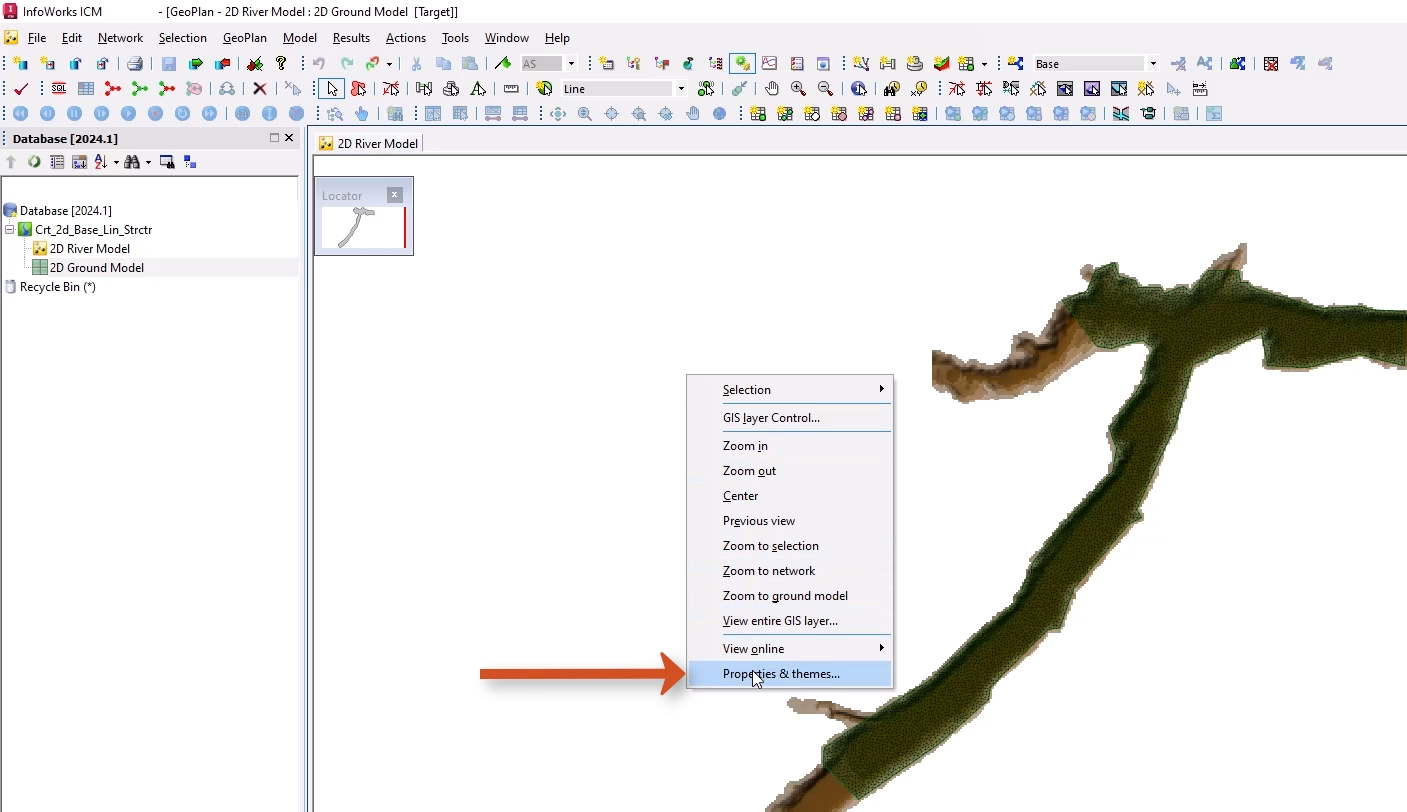
It may be helpful to adjust the Ground Model theme to better see the objects and mesh:
- Right-click the GeoPlan and select Properties & Themes.
- On the Layers and Themes tab, for the Ground Model object layer, in the Theme column, click Edit.
- In the Layer Theme Editor, expand the Map Type drop-down and select Ground Model - Transparent.
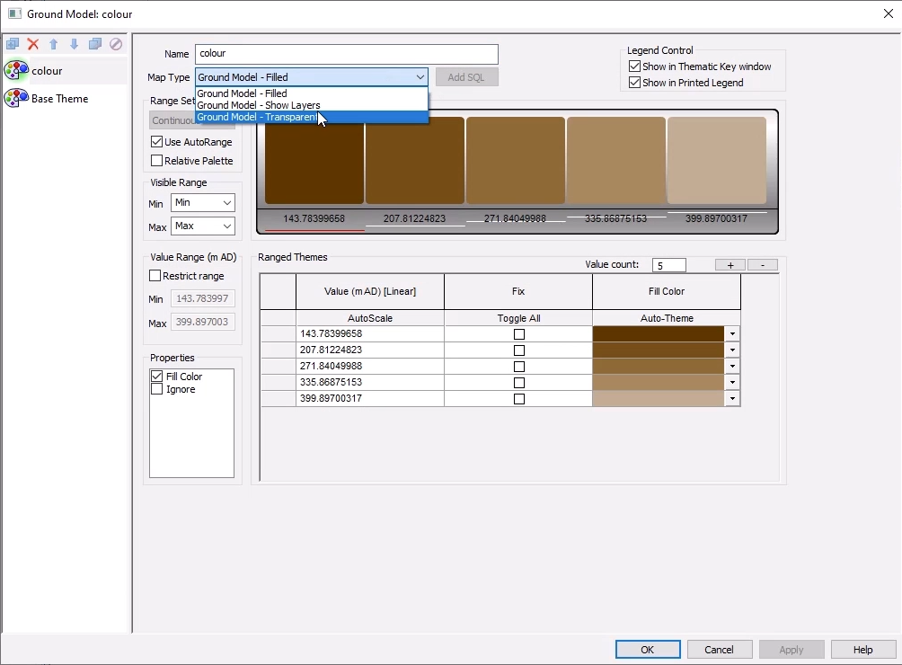
- Click OK.
- Click OK again to close the GeoPlan Properties and Themes dialog box.
Now, locate the area to add the 2D base linear structure:
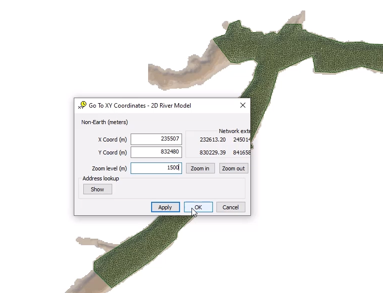
- In the GeoPlan Tools toolbar, click Go to xy coordinates.
- In the popup, set the X coordinate to 235507.
- Set the Y coordinate to 832480.
- Set the Zoom level to 1500.
- Click OK.
The GeoPlan zooms in to these coordinates. Now, draw a dam structure across the riverbed in this area:
- From the GeoPlan Tools toolbar, expand the New Object Type drop-down and select Line.
- Click New Object.
- Draw a line across the width of the 2D zone, from left to right.
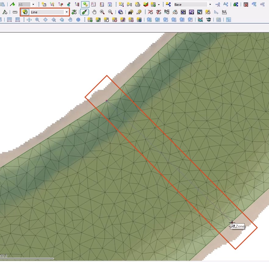
Ensure that the line is bigger than the channel bed, or flow will be able to pass around it. The snap tool can be used to snap to the 2D zone vertices on the edge of the 2D zone domain.
- Double-click to finish the line.
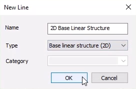
- In the New Line popup, add a Name, such as “2D Base Linear Structure”.
- Set the Type to Base linear structure (2D).
- Click OK.
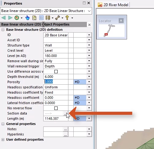
This example sets up a wall with a level of 180 mAD to act as a dam. It can also be set up for the wall to be removed once a threshold is met within the simulation.
- In the Properties window for the base linear structure, set the Structure type to Wall.
- Set the Crest level to Level.
- Set the Level to 180.
- Set the Remove wall during simulation option to Fully.
- Set the Depth threshold to 6.
- In the Section data field, click the More (…) button to view the profile applied to the structure.
- In the Section data window, right-click the graph and select Show Ground Model to see the ground model represented by a green line.
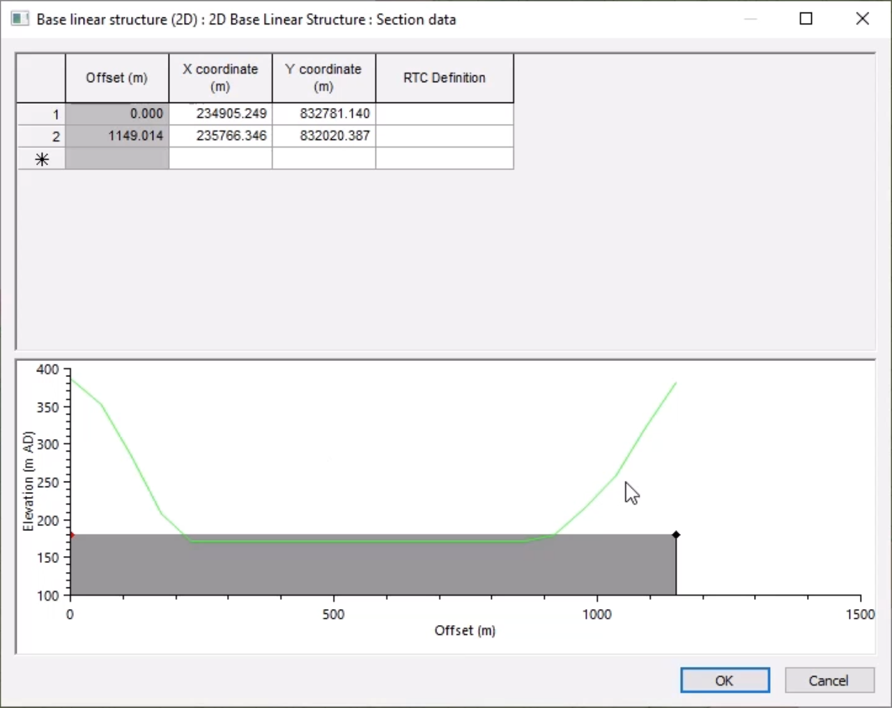
The 2D element level overrides any levels higher than the structure.
- Click OK to close the Section data window.
Since changes were made, the 2D zone needs to be re-meshed:
- Double-click an area of the 2D zone.
- From the Multiple Selection popup, select 2D Zone.
- Click OK.
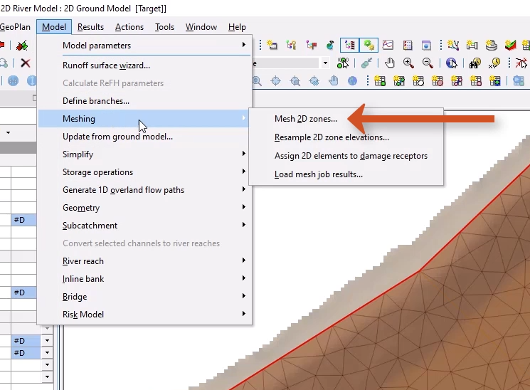
- From the Model menu, select Meshing > Mesh 2D zones.
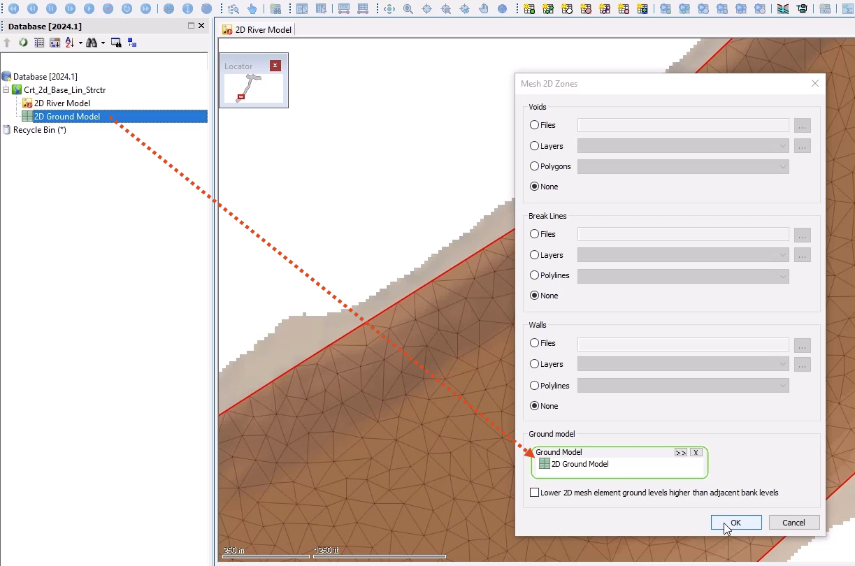
- In the Mesh 2D Zones dialog box, if the Ground Model group box is not populated, from the Database, drag the 2D Ground Model and drop it into the Ground Model group box.
- Click OK to mesh the 2D zone.
- In the Schedule Job(s) popup, click OK.
- From the Window menu, select Job control window to display the status of the mesh job and some information on the generation.
Once the mesh has completed, it can be loaded into the model:
- From the Job control window, click the Mesh ready status to open the Manage mesh results window.
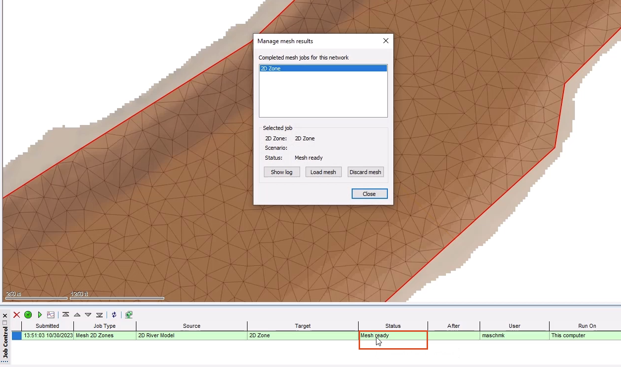
- Click Load mesh.
- Click Close.
The 2D base linear structure is incorporated into the mesh.
- Click Validate to make sure there are no errors in the Base network.
- Click OK.
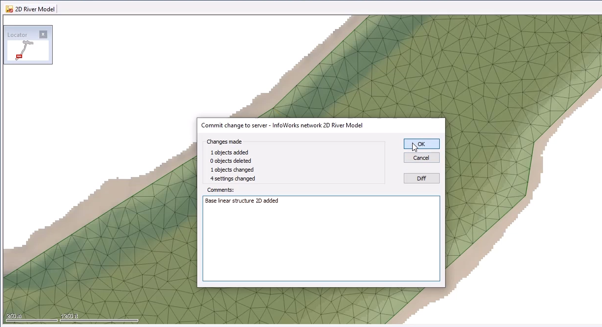
- Click Commit changes to database to save the changes.
- Add a comment, such as “Base linear structure 2D added”.
- Click OK.