Completing the hydraulic design in InfoDrainage
Configure the stormwater design options for subcatchments and complete the hydraulic design in InfoDrainage.
Tutorial resources
These downloadable resources will be used to complete this tutorial:
Step-by-step
InfoDrainage is very powerful in its ability to calculate the appropriate sizes and types of stormwater drainage system elements for you. This is why, once you have successfully imported a CAD file that was started in Civil 3D, you can complete the hydraulic design in InfoDrainage.
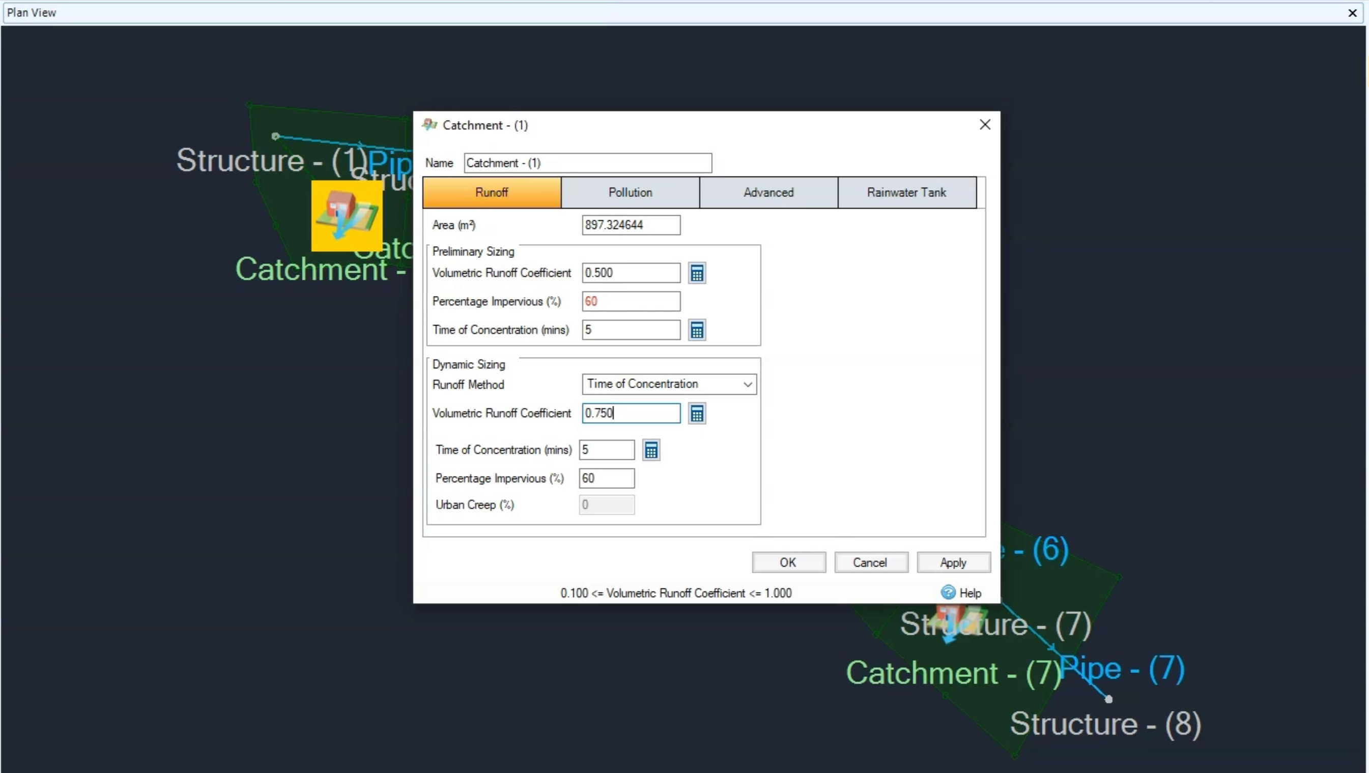
- Review the data for the first catchment. Place your cursor over the catchment icon and click to open its properties.
To change the percentage impervious value for all the catchments in the model and set the Preliminary Percentage Impervious value to 60:
- In the Catchment – (1) dialog box, Runoff tab, set Percentage Impervious to 60.
- Set Time of Concentration to 5 minutes.
- Set the Volumetric Runoff Coefficient to 0.75.
- Click OK.
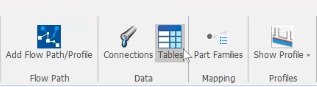
- On the ribbon, Build tab, Data panel, click Tables.
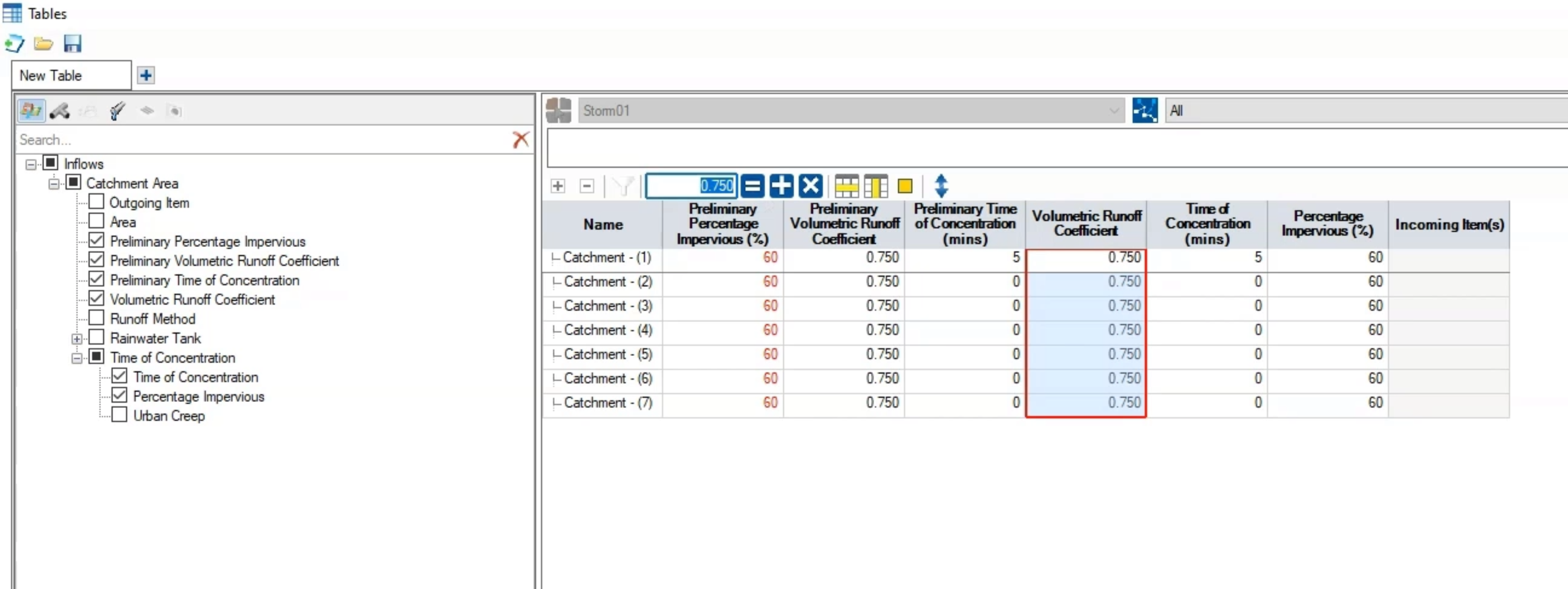
- In the Tables dialog box, select the Inflows tool.

- In the left pane, expand the Inflows node.
- Expand the Catchment Area node.
- Enable Preliminary Percentage Impervious, Preliminary Volumetric Runoff Coefficient, and Volumetric Runoff Coefficient.
- Expand Time of Concentration and enable Percentage Impervious.
- In the Percentage Impervious column, select the first cell, then click and drag to select all the cells.
- In the toolbar, enter 60 into the box.
- Click the equals sign (=).
To set the Volumetric Runoff Coefficient:
- Select all the cells under the Volumetric Runoff Coefficient.
- Repeat steps 13 and 14 to change those values to 0.75.
Note: the Area values have all been calculated for you.
- Click OK.
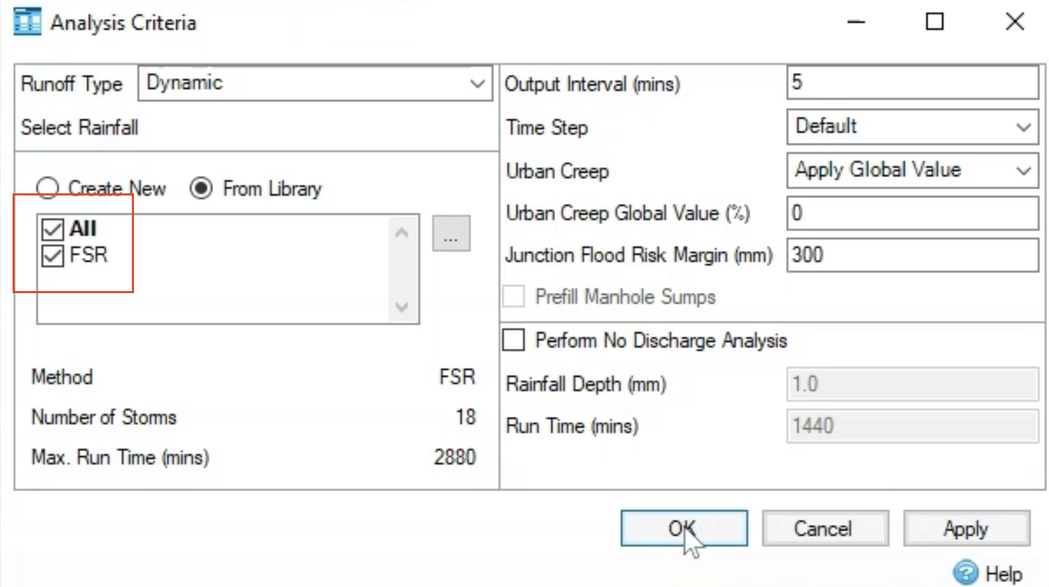
To configure the analysis:
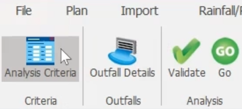
- On the ribbon, Analysis tab, Criteria panel, click Analysis Criteria.
- In the Analysis Criteria dialog box, select both the All and FSR rainfall studies, and then click OK.
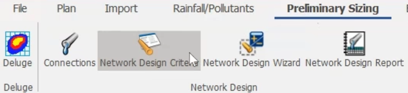
To set up the preliminary sizing for the pipes:
- On the ribbon, Preliminary Sizing tab, Network Design panel, click Network Design Criteria.
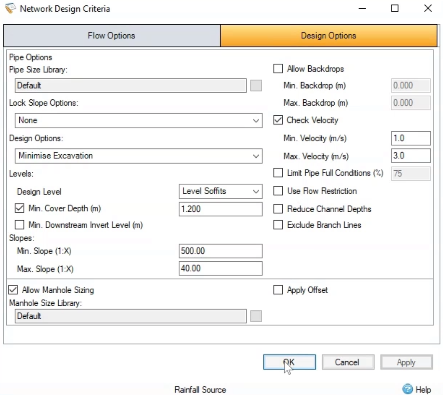
- In the Network Design Criteria dialog box, Flow Options tab, expand the drop-down and select FSR.

- Click the Design Options tab.
- Accept the defaults and click OK.
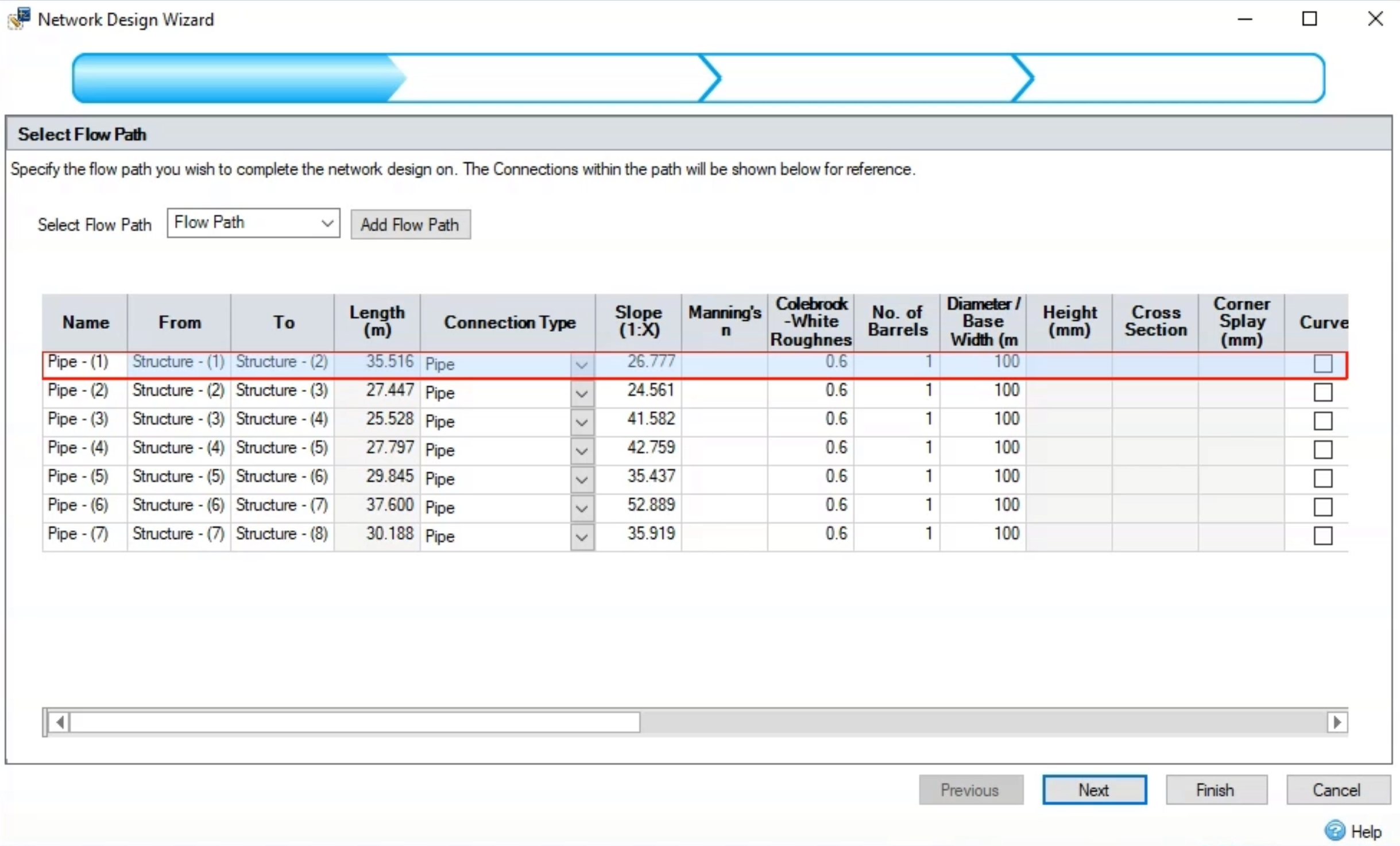
- On the ribbon, Preliminary Sizing tab, Network Design panel, open the Network Design Wizard.
- On the Select Flow Path page, select which pipes you want to design.
- Click Next.
- On the Enter Flow Criteria page, accept the defaults for the rainfall and click Next.
- On the Enter Design Options page, accept the default options for the flow path and its network and click Next.
- On the Summary of Changes page, review the changes made during the network design.
- Click Finish.

- Review the summary in the Network Design Report dialog box.
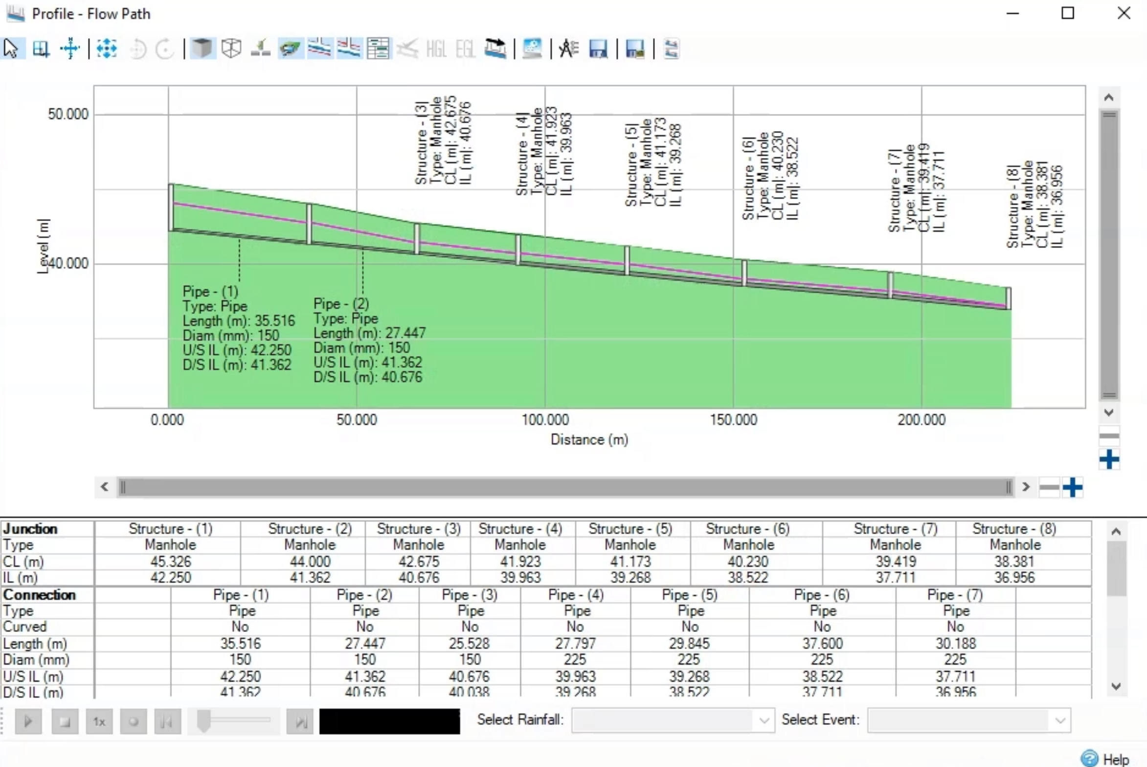
- Review the pipe profile and the changes to the flow path.
- In the Tree View, click Flow Path.
- Right-click Flow Path and select Show Profile.
Note: In the Profile – Flow Path dialog box, there is a different gradient, and the pipes are different sizes, both of which indicate the system has now been hydraulically designed.
- To see the system data in greater detail, on the ribbon, Build tab, Data panel, click Tables.
- To see the pipe data, click the Connections tab.
- Review the table that populates with the new pipe data. Notice the Diameter / Base Width column contains the new pipe sizes.
- Click OK.

- Save the network as Hydraulic Design
This InfoDrainage network can now be imported back into Civil 3D to complete the design.