Create and modify long sections
Create and modify long sections (section views).
Tutorial resources
These downloadable resources will be used to complete this tutorial:
Step-by-step guide
A long section (or section view) window displays a cross-section view through the length of a selected run of network objects. This long section view has many uses:
- Inspect a run of nodes and links
- Edit network objects by accessing their object properties window
- View simulation results
- Insert a node into a link displayed on the view
To complete this exercise, create a new network and import the 1D Sewer Network.isfm snapshot file, or open an existing sewer network model on the GeoPlan.
To use the Long Section Pick tool to create a long section window:
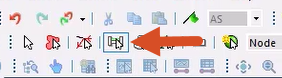
- In the menu bar, select GeoPlan > GeoPlan tools > Long Section pick,
OR in the GeoPlan Tools toolbar, click the Long Section pick tool.
- On the GeoPlan, zoom in to a specific area and select a run of pipe.
The long section window opens:
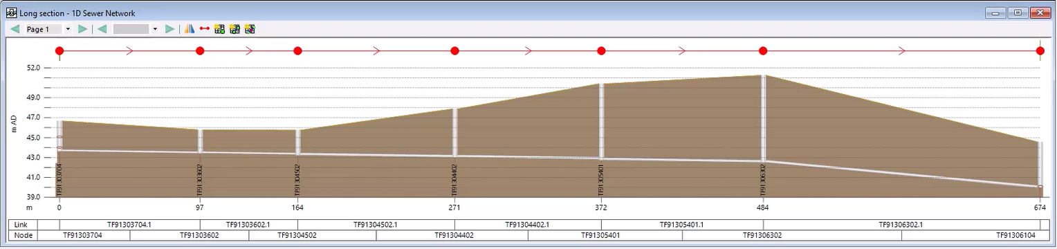
- Click the title bar of the long section window to make it the currently active view.
A Section menu appears in the menu bar. To change the labels that are displayed:
- Open the Section Properties dialog box by selecting Section > Properties,
OR right-click the long section and select Properties.

The Content tab allows you to change how the long section is viewed and choose what grid labels are displayed along the X-axis.
To set the labels that are displayed:
- On the Content tab, in the Grid Labels group box, click Field Settings.
- In the Network Label Field Settings dialog box, in the list of object types, select Node.
- On the right, in the list of fields, select ground_level and flood_level.
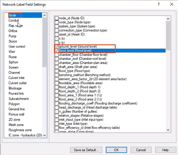
- Change the object type to Conduit.
- In the list of fields, select conduit_height.
- Click OK.
- In the Section Properties dialog box, click Apply to update the view.
The selected fields now appear at the bottom of the view with any associated flag colors.
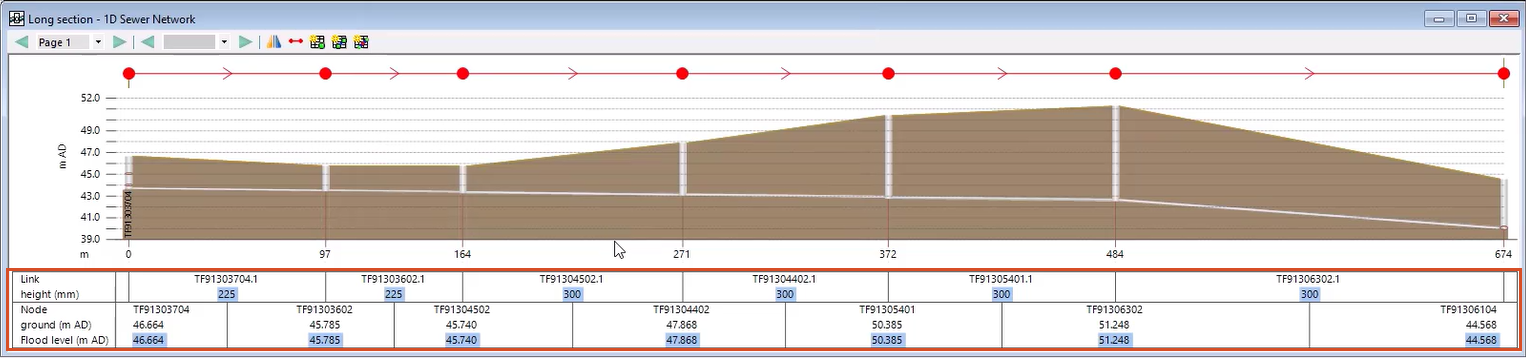
- Click OK to close the Section Properties window.
To open the property sheet for any object in the long section:
- In the GeoPlan Tools toolbar, click Properties, and then click any node in the section window.
OR, click the Select tool, and then double-click the node.
The Object Properties window displays the property sheet for the selected object to view or edit the object data.
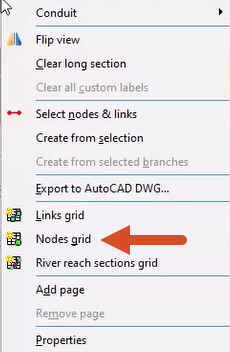
- Right-click the long section for a menu of additional options. For example, select Nodes grid to open an object grid containing only the objects in the long section.
- Close the grid window.
Notes:
- Several long section windows can be open at the same time.
- If a long section window contains multiple pages, the page number appears in the toolbar with Next and Previous arrow buttons to scroll through the pages.
- Any theme applied to the GeoPlan is replicated in the long section.