Gear generator - Exercise
Generating gears and bearings
Gears can be placed around or is part of the shaft. There's also a capacity for incorporating existing gears into the calculation. The gears can be spur gears, worm gears, or bevel gears.
There are multiple ways to design the gear components. You can develop gears based on number of teeth, center distance catch, module, or a combination. You can also validate the design by calculating based on the loads and materials for the gears.
- Open the Belt Driven Reducer – Gears.iam file from the Workspace folder.
- Switch to the Design tab, hold the Alt key, and start the Spur Gears generator tool from the Power Transmission panel.
Note: Holding the Alt key will start the tool with the default shaft configuration.
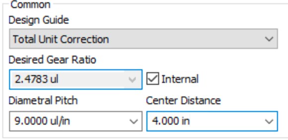
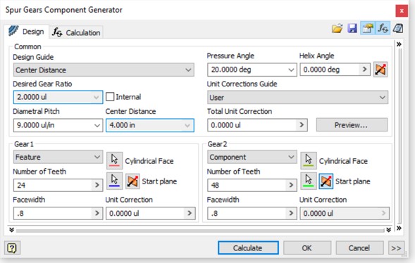
- Because the center distance is fixed, change the Design Guide to Total Unit Correction.
- Set the Diametral Pitch to 9 ul/in and make sure the Center Distance is 4.0.
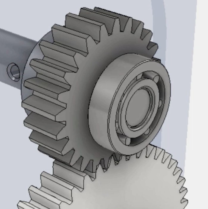
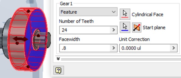
- In the Gear 1 definition, set the type of gear to Feature, set the number of teeth to 24 and the Facewidth to .8.
- Select the outer face of the large segment for the Cylindrical Face and the face closest to the short segment for the Start plane.
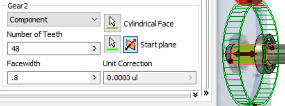
- Set Gear 2 to Component, the number of teeth to 48 and the Facewidth to .8.
- Select the face of the lower shaft for the Cylindrical Face and the same face on the top shaft for the Start plane.
Note: It might be necessary to flip the Start plane to align the gears.
- Click Calculate to update the Desired Gear Ratio.
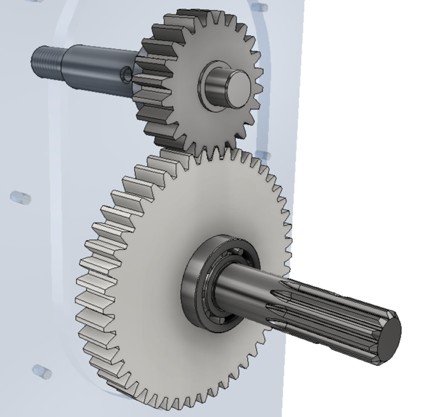
- Click OK to generate the part files from the gears.
- Click OK again to create the gears in the design.
Bearings are normally selected from standard sized based on performance in conjunction with size limitations for the design. The Bearing Generator can be used to limit available options for the correct bearing on size, engineering performance, or both offering you a list of bearings that meet your needs and then placing them in the assembly.
- Hold the Ctrl key and start the Bearing generator tool from the Power Transmission panel.
Note: Holding the Ctrl key will start the tool with the default shaft configuration.

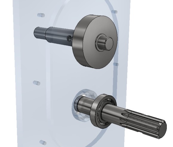
- Select the outside face of the last segment of the top shaft for the Cylindrical Face reference.
- Pick the flat face of the short segment for a Start Plane.
Note: Pick the flip option if the preview is not over the end segment of the shaft.
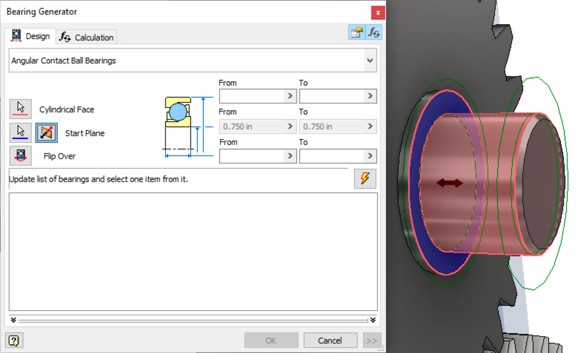
- Click on the Bearing type near the top of the tab to open a dialog that sets the type.
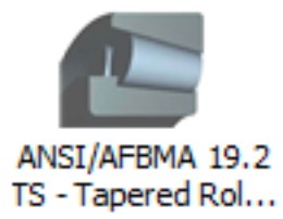
- Click the Category pull-down on the right and select Tapered Roller Bearings.
- This will present a list of specific bearing types. Click on the ANSI/SFMBA 19.2 TS – Tapered Roller Bearing type.
- This will generate a list of bearings of this standard in all available sizes.
- Set the Outer Diameter values for From to 1.7 and To to 1.8.
- Click the Update icon to filter the list of available bearings.

- Select the 05075 05175 from the designation list, click OK to select the bearing, and click OK again generate the bearing in the design.