Belt drive design and calculations
Any referenced datasets can be downloaded from "Module downloads" in the module overview.
Belt generator - Exercise
Adding a belt and key
Belts – like other Design Accelerators, there is more than one type of belt can be added to the machine that can be created using the V-belts, synchronous belts, and roller chain tools. These components can only be purchased in specific sizes and increments (links).
- Open the Belt Driven Reducer – Belt Drive.iam file from the Workspace folder.
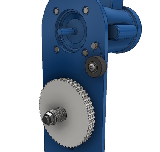
- Switch to the Design tab and start the Synchronous Belts generator tool from the Power Transmission panel. It may be under the V-Belts tool.

- Set the belt type to H.
- Pick the face of the existing Pulley to set the Belt Mid Plane. Set the mid plane back .49 from the front face.
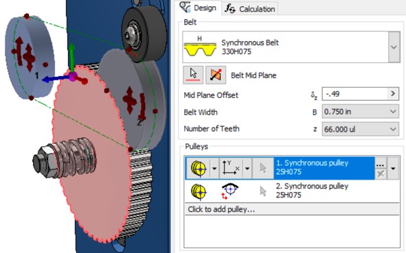
- Set the first (top) Pulley to be Fixed position by selected geometry and select the shaft of the motor.
- Double-click the description and set the number of Teeth to 24. Click OK to close the Pulley Properties dialog.
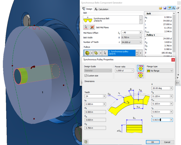
- Set the second Pulley type to Existing and click on a tooth face of the Pulley that was already in the design.
- Pick on Click to add pulley…, choose a pulley type, and then change the new pulley to Virtual.
- Click and drag the new third pulley to be the second position in the dialog.
- Change the Pulley type to Virtual and move it into an approximate position.
- Selecting the curved arrow can change the third pulley from inside to outside.
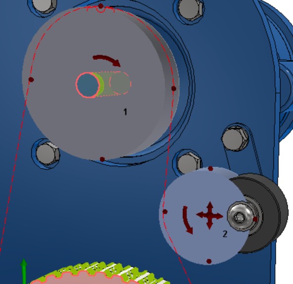
- Change the Pulley type to Virtual and move it into an approximate position.
- Set the Pulley Placement Guide option to Rotation driven sliding position.
- Pick the center of the arm the modeled idler will rotate on.
- Set the Pulley Diameter and the Arm Radius to 2 inches.
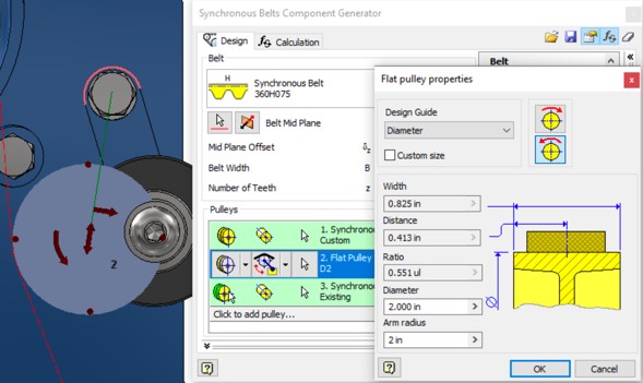
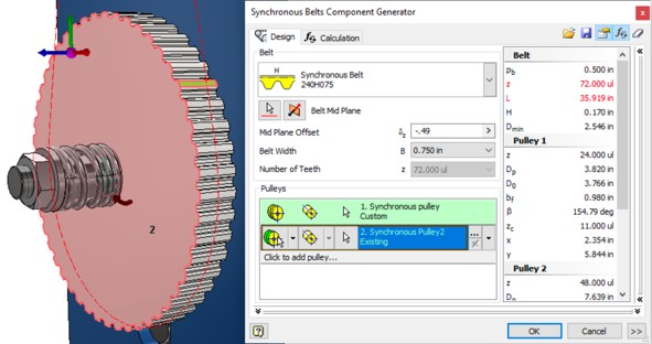
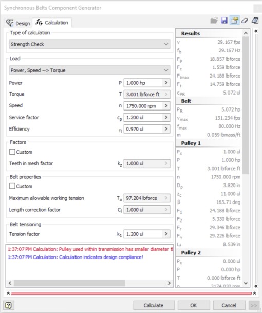
- Run a calculation using 1hp and 1,750 rpm.
- The calculation should display an error over a pulley size.
- Update the Idler pulley size to 2.5 inches.
- Expand the dialog and change the Create Belt As value to Detailed.
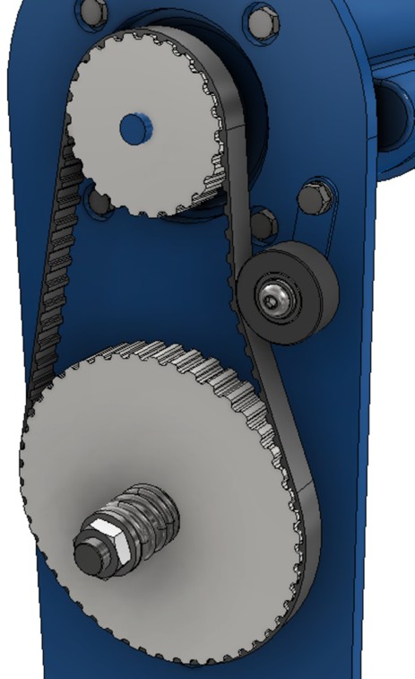
- Click OK to create the new pulley data and OK again to generate the top pulley and belt.
Keys can be created as standalone objects, while adding a groove to a shaft, and/or a hub.
- Switch to the Design tab, hold the Ctrl key and start the Key generator tool from the Power Transmission panel.
Note: Holding the Ctrl key will start the tool with the default shaft configuration.
- Set the Key type to Rectangular or Square Parallel Keys with the .1875 x .1875 - .375 size.
- In the Shaft Groove, select the middle option and set Reference 1 to the motor shaft surface and Reference 2 as the end of the motor shaft.
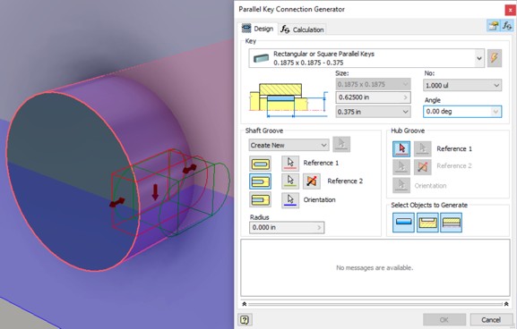
- Select the front face of the pulley for Reference 1 of the Hub Groove.
- Choose the rounded edge of a Pulley tooth for Reference 2.

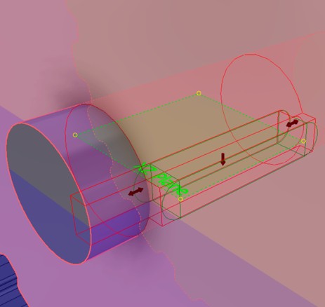
- Drag the length of the Key to 1. Experiment with the angle of the key and the position.
- Click OK to generate the Key and Grooves.
Was this information helpful?