Understanding flush zones and the Flush Zone Manager
Any referenced datasets can be downloaded from "Module downloads" in the module overview.
Transcript
00:03
With InfoWater Pro UDF, you can create flush zones to represent pressure zones, maintenance areas, subdivisions,
00:13
downtown areas, and new developments in your hydraulic model.
00:18
All hydrants and requirements in a flush zone are under the same user-defined characteristics,
00:24
such as minimum flush velocity and maximum flush length.
00:29
You create flush zones with the Flush Zone Manager.
00:34
To open the Flush Zone Manager, from the Model Explorer, open the UDF tab and click Flush Zone Manager.
00:43
The Flush Zone Manager dialog is comprised of a few main areas:
00:49
the toolbar, the Flush Zones group box, and the Flush Zone Characteristics group box.
00:56
The Flush Zones group box lists any flush zones you have created, including an ID and a user-defined description for each zone.
01:07
To edit the description of the currently selected flush zone, click the Edit Flush Zone Description button in the toolbar.
01:16
All fields in the Flush Zone Manager must be populated.
01:21
If certain Flush Zone Characteristics are not important to the analysis,
01:26
it is recommended that you use a large number for maximum characteristics, or a small number for minimum characteristics.
01:36
UDF results are checked against the following characteristics in the selected flush zone.
01:43
A warning is generated if one or more constraints is violated during a sequence simulation:
01:50
Minimum Flush Velocity:
01:53
Enter the minimum desired velocity for target pipes in the flush zone.
01:60
Maximum Flush Volume:
02:02
Enter the maximum total volume of water to be flushed out of the hydrant.
02:08
Enter a value of 0 to ignore this characteristic.
02:14
Maximum Flush Length:
02:16
Enter the maximum total length of pipe to be flushed.
02:21
Enter 0 to ignore this characteristic.
02:25
Minimum Residual Pressure:
02:28
Enter the minimum residual pressure to be maintained at the hydrant being flushed.
02:34
Minimum System Pressure:
02:36
Enter the minimum static pressure to be maintained at all nodes contained in the Flush Area.
02:44
Minimum Shear Stress:
02:47
The hydraulic shear stress at the pipe wall can also be used as a criterion for flushing.
02:54
The minimum shear stress will be used as a parameter to determine a successful flushing routine.
03:01
A successful simulation will result when the minimum shear stress value is met or exceeded.
03:09
Enter 0 to ignore this characteristic.
03:13
Expand the Flush Area drop-down
03:16
to pick a selection set representing the flush zone consisting of any combination of network components.
03:24
During a UDF simulation, the minimum system pressure
03:29
is compared to the pressure calculated at each junction in the selection set defining the flush area.
03:36
Low pressure warnings will only be generated when low static pressure occurs at one or more junctions in this selection set;
03:46
low pressures outside this selection set will not be considered.
03:51
Use the Highlight Color options to customize the highlight colors of a selected zone,
03:58
and to highlight the currently selected zone on the map.
04:03
Click Reset to reset the map to the default display.
04:08
All valves listed in the Closed Isolation Valves box will remain closed for each flush sequence within the selected flush zone.
Video quiz
Required for course completion
With InfoWater Pro UDF, flush zones can be created to represent pressure zones, maintenance areas, subdivisions, downtown areas, and new developments in a hydraulic model. All hydrants and requirements in a flush zone are under the same user-defined characteristics, such as minimum flush velocity and maximum flush length.
To open the Flush Zone Manager, from the Model Explorer, UDF tab, click Flush Zone Manager.
The Flush Zone Manager dialog box is comprised of the toolbar, the Flush Zones group box, and the Flush Zone Characteristics group box.
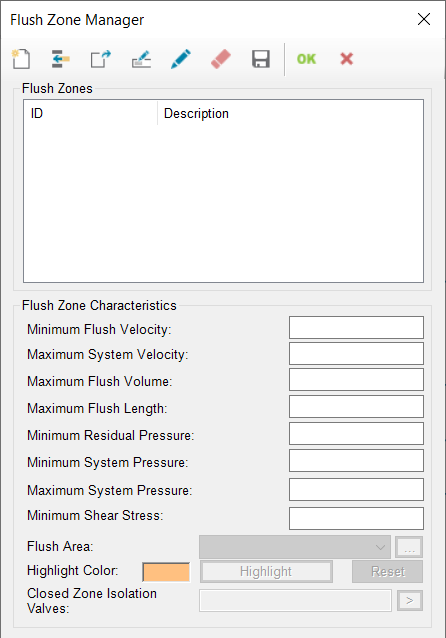
Flush Zones:
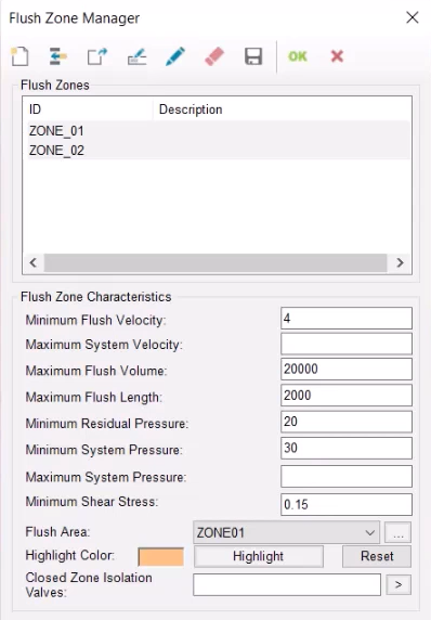
The Flush Zones group box lists any flush zones created, including an ID and a user-defined description for each zone.
To edit the description of the currently selected flush zone, from the toolbar, click Edit Description.
Flush Zone Characteristics:
All fields in the Flush Zone Manager must be populated. If certain Flush Zone Characteristics are not important to the analysis, it is recommended to use a large number for maximum characteristics, or a small number for minimum characteristics.
UDF results are checked against the following characteristics in the selected flush zone. A warning is generated if one or more constraints is violated during a sequence simulation:
- Minimum Flush Velocity: Enter the minimum desired velocity for target pipes in the flush zone.
- Maximum Flush Volume: Enter the maximum total volume of water to be flushed out of the hydrant. Enter a value of 0 to ignore this characteristic.
- Maximum Flush Length: Enter the maximum total length of pipe to be flushed. Enter 0 to ignore this characteristic.
- Minimum Residual Pressure: Enter the minimum residual pressure to be maintained at the hydrant being flushed.
- Minimum System Pressure: Enter the minimum static pressure to be maintained at all nodes contained in the Flush Area.
- Minimum Shear Stress: The hydraulic shear stress at the pipe wall can also be used as a criterion for flushing. The minimum shear stress will be used as a parameter to determine a successful flushing routine. A successful simulation will result when the minimum shear stress value is met or exceeded. Enter 0 to ignore this characteristic.
Expand the Flush Area drop-down to pick a selection set representing the flush zone consisting of any combination of network components.
During a UDF simulation, the minimum system pressure is compared to the pressure calculated at each junction in the selection set defining the flush area. Low pressure warnings will only be generated when low static pressure occurs at one or more junctions in this selection set; low pressures outside this selection set will not be considered.
Use the Highlight Color options to customize the highlight colors of a selected zone, and to highlight the currently selected zone on the map.
Click Reset to reset the map to the default display.
All valves listed in the Closed Zone Isolation Valves box will remain closed for each flush sequence within the selected flush zone.