Getting started with templates
Any referenced datasets can be downloaded from "Module downloads" in the module overview.
Templates and styles - Exercise
- Open the drawing C:\Autodesk Learning\Setup C3D Projects\Course 2 - Drawing Templates – Styles\Try-it-2A.dwg. This drawing has one XREF drawing (Existing Basemap.dwg) and one data reference of the XGND surface.
- Select the XGND surface by clicking on a contour. The entire surface highlights.
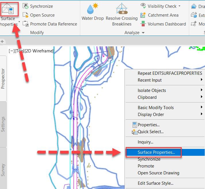
- Right-click and select Surface Properties or pick the command from the ribbon.
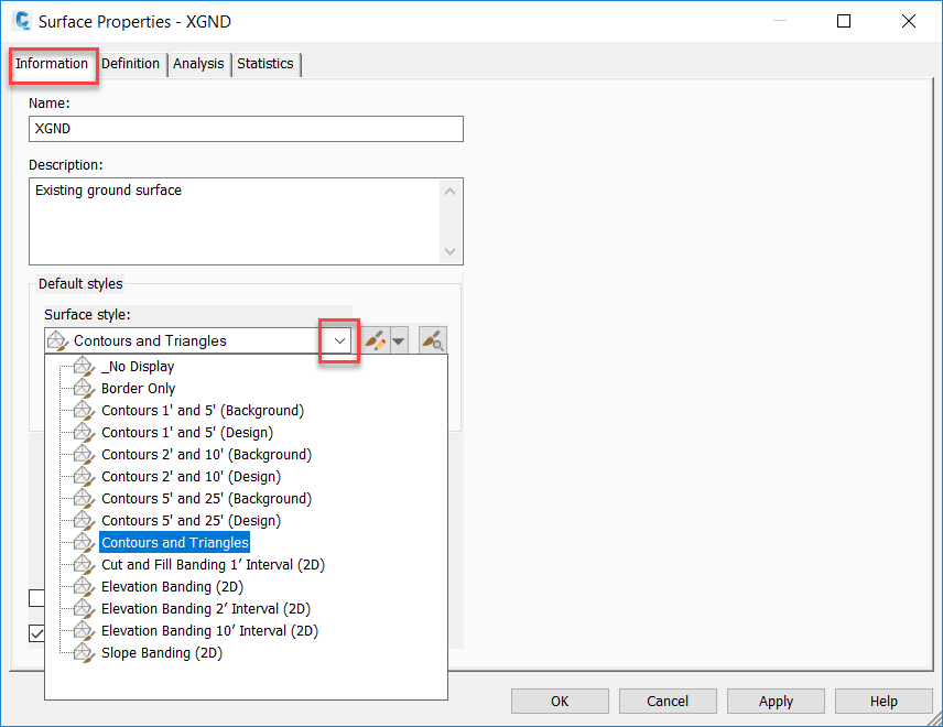
- In the Surface Properties dialog box>Information tab, in the Default styles area, select Contours and Triangles from the Surface style drop-down list and click Apply. Note the change to the surface appearance.
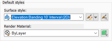
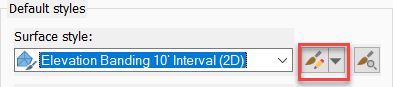
- Change the Surface style to Elevation Banding 10' Interval (2D) and click Apply. Again, note the change to the surface appearance.
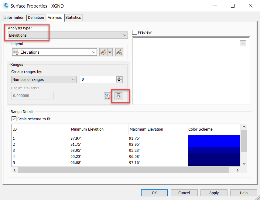
- In the Surface Properties dialog box, select the Analysis tab. Ensure that the Analysis type is set to Elevations, and click the down arrow icon (Run analysis) to run the analysis, as shown in the image below. Note the Minimum and Maximum Elevations and Color Scheme used to display the elevations in the model.
- Return to the Information tab and click Edit Current Selection next to the Surface style drop-down list to open the Surface Style dialog box.
- On the Display tab, turn on the lightbulb in the Visible column next to the Triangles and Border
component types and click Apply.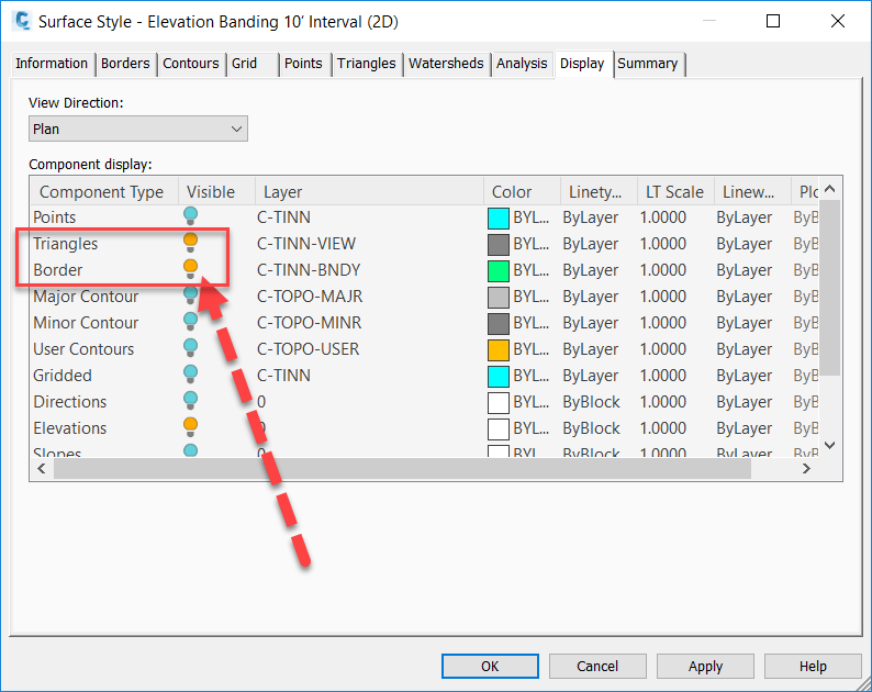
- Note that the surface now is displaying the TIN triangles and the border.
- On the Information tab, change the Surface style back to Contours 1' and 5' (Background) and click OK.
- Save the drawing.
- Open the drawing C:\Autodesk Learning\Setup C3D Projects\Course 2 - Drawing Templates – Styles\Try-it-2B.dwg.
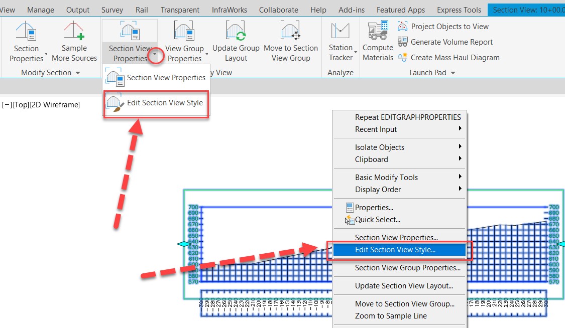
- Zoom in to one of the section views and select it.
- Right-click and select Edit Section View Style or pick the command from the drop-down list in the ribbon, as shown in the image below.
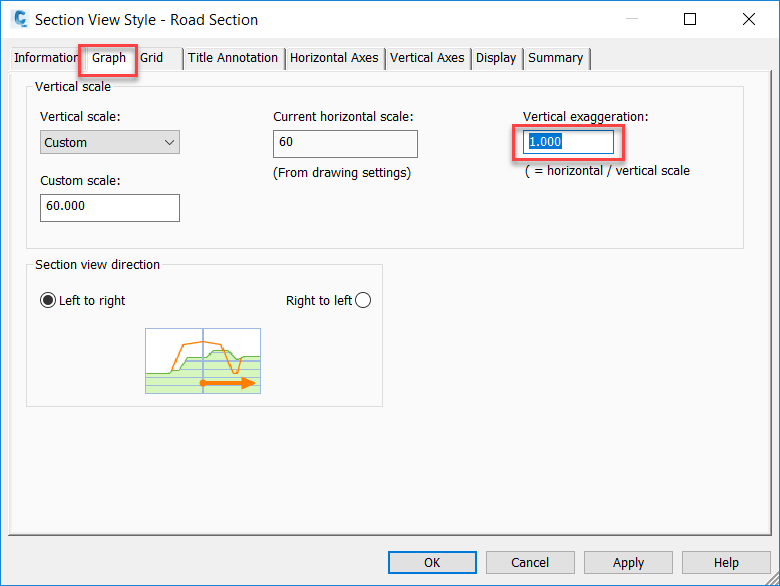
- In the Section View Style dialog box, browse through each tab along the top and note the variety of items you can change and configure for the section view style. In particular, note the Vertical exaggeration option on the Graph tab, as shown in the image below.
- Click Cancel to close the dialog box without making any changes.
- Zoom and pan over to the corridor.
- Select the corridor.
- Right-click and select Corridor Properties or pick the command from the ribbon.
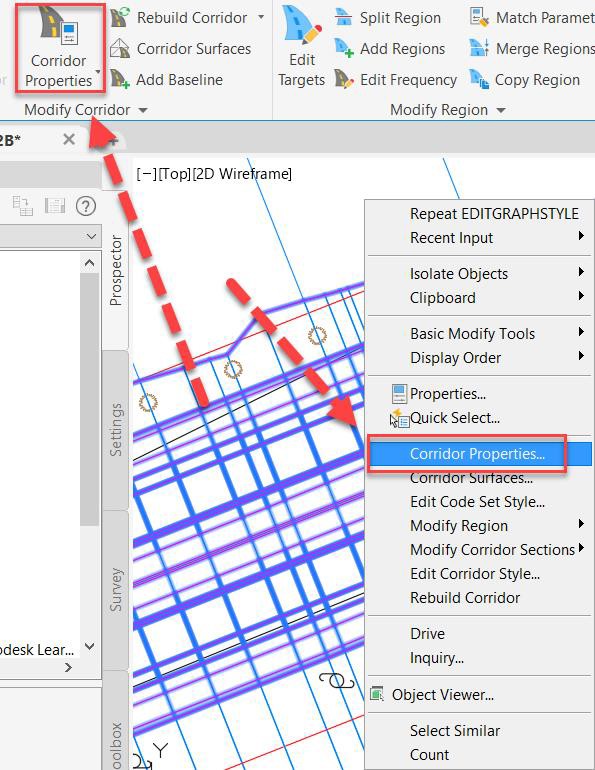
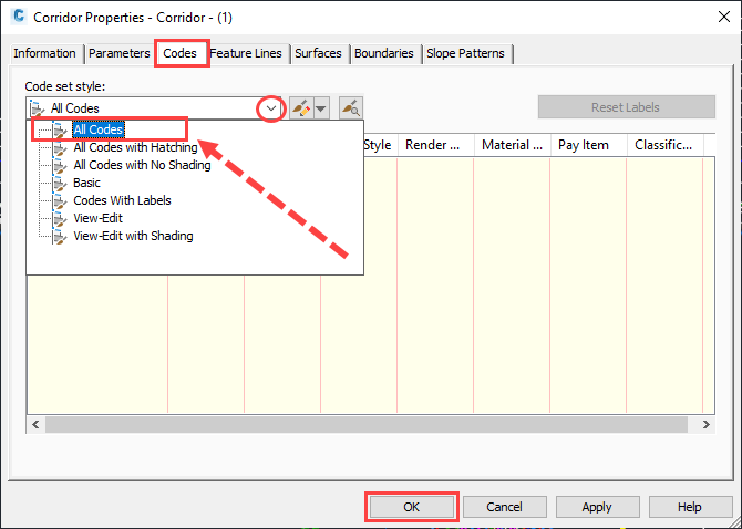
- In the Corridor Properties dialog box>Codes tab, select All Codes from the drop-down list and click OK.
- When prompted, select Rebuild the Corridor. The corridor is rebuilt with different colors for the links and shapes of the corridor.
- Zoom and pan to a section view and note that it too has changed when the code set was changed.
- Close the drawing without saving it.