Creating surfaces from classified data
Any referenced datasets can be downloaded from "Module downloads" in the module overview.
Creating surfaces from classified data - Exercise
Task 1: Create surface using classification - Raster method
This method uses filtered point cloud data. It will use filters by classification.
- Continue from the drawing and the point cloud data used in the exercise from the second course objective.
- Return to Wireframe display so that the point cloud is visible and selectable.
- Enter at the command line MAPCREATPCSURFACE.
- Use a crossing window to select the edge of the point cloud.
- The Create Surface form Point Cloud dialog box is launched – click on Filter.
- Select Ground and OK.
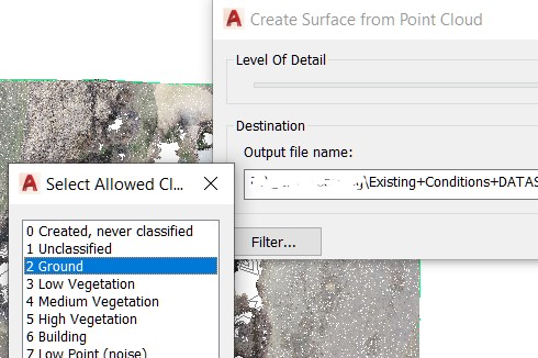
- Browse to a folder that you chose and create a file name for the raster file that will be created.
- Select OK to begin the geoTif raster file creation.
- After processing the points the raster results will be displayed. Change the view style to 2D Wireframe to see the raster data more clearly.
- On the Prospector tab of the Toolspace, right-click on the Surface collection and click on Create Surface from DEM.
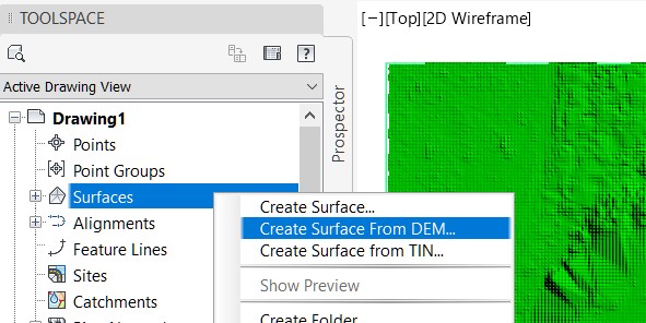
- Browse to and select the file that was just created – it will have a .tif extension.
- Close the Event View after reading the reason for the notices: points ignored – no z value.
- To turn off the display of the raster data we will have to use the Map Task Pane. Enter MAPWSPACE at the command line.
- Select ON option.
- On the Display Manager tab, the check mark in front of the raster file name can be toggled on and off to control the display.
- To delete the raster data source connection to this drawing, right-click on the name and select Remove Layer.
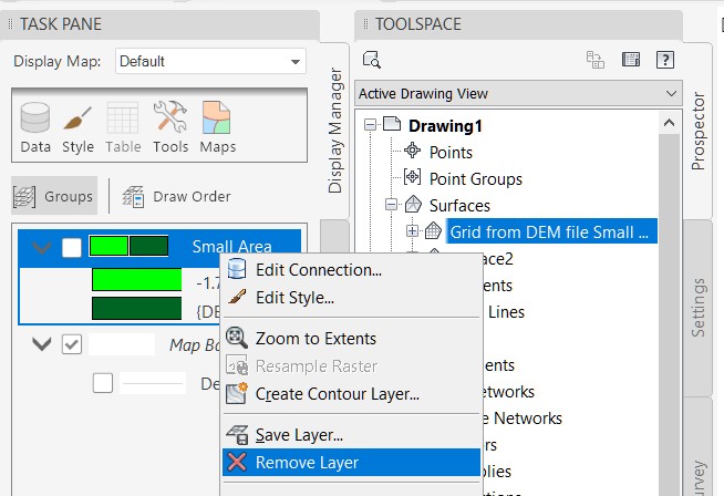
Note: the raster file can be disconnected from this drawing, however the file cannot be deleted as it is a data source that is being referenced to build the surface that appears in this drawing and must remain linked to the surface.
Task 2: Compare surfaces
- Change the surface style of the DEM surface. On the Prospector tab, click and expand the Surface collection. Right-click on the Grid from DEM surface and select Surface Properties.
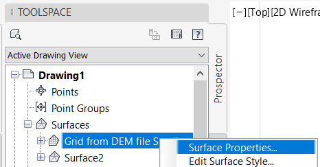
- On the Information tab, change the Surface Style to Contours 1m and 5m (Design).
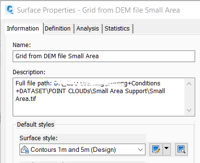
- On the Statistics tab, expand the General group and note the number of points in the surface. (This is more than the recommended maximum and a GRS overflow file might be created.)
- Click OK to close the Surface Properties dialog box.
- Draw a LINE across an area of interest, select the line and right click to select Quick Profile.
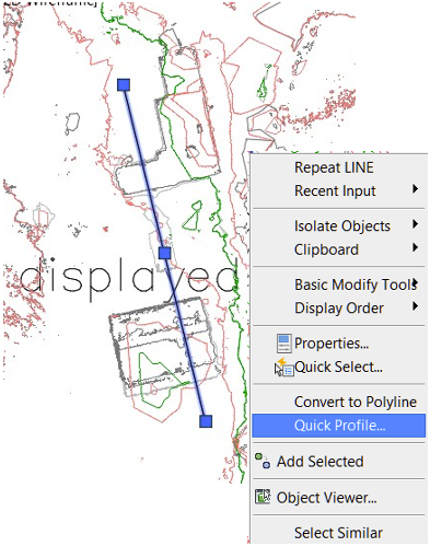
- Accept the defaults in the Create Quick Profile dialog box. Click OK.
- Move away from the surface view and pick a point to locate the profile view.
- Close the Event View after reading the reason for the notices: This is a temporary object.
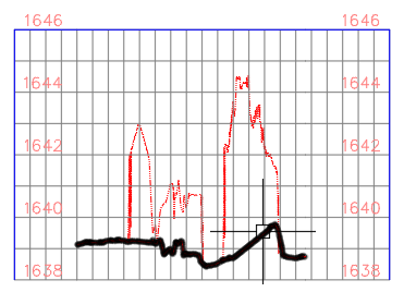
- Hover over each of the profiles in the profile view to highlight each, this shows the difference between filtered and non-filtered ground data.
- Experiment with moving and changing the line which defines the profile and see the dynamic updates in the profile view.
- Erase or delete the line to remove the Quick Profile.
It is not necessary to save this drawing.
Conclusion
There are several ways to create existing ground terrain. It is important to review the resulting data and methods to determine which surface method is best for the original data that you are using. Depending on the data, the methods, and the manual clean-up your model can represent the existing conditions.