Adding lighting to a rendering scene
Any referenced datasets can be downloaded from "Module downloads" in the module overview.
Add lighting to prepare your view for rendering - Exercise
Revit won’t just light up a room when you hit the Render button. If there are no lights, your room is going to be dark. Therefore, you need to add and configure lights in your model before you render.
To add and configure lighting for your model, follow these steps:
- Open Revit.
- Open the Small Medical Center.rvt model from your project files. If you did not complete the previous exercise, open Small Medical Center-Lights.rvt instead.
- In the Project Browser, select the SECOND FLOOR BREAKROOM 3D view to make it the current view if not already active. Note that there are no lights in the breakroom.
- Open the SECOND FLOOR reflected ceiling plan.
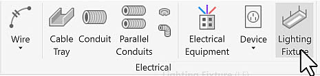
- In the Systems tab>Electrical panel, click Lighting Fixture.
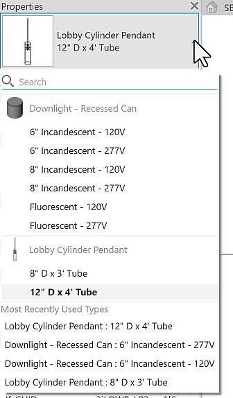
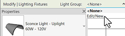
- Browse through the available light fixtures currently in the model by using the Type Selector in Properties, as shown below.
- There is nothing really suitable, so you will need to load a fixture. In the contextual tab, click Load Family.
- In the Lighting\MEP\Interiors folder, select Troffer Light – 2x2 Parabolic.rfa.
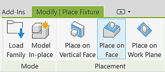
- In the contextual tab, select Place on Face.
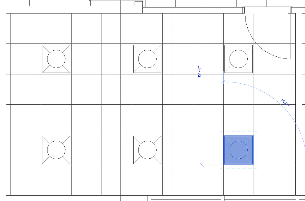
- Select a horizontal ceiling grid line to place the fixture.
- Click Modify to finish the command.
- Type AL to start the Align command. Select a vertical ceiling grid line as the destination and a vertical line on the light fixture to align it.
- Click Modify to finish the command.
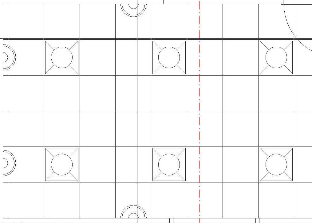
- Copy the light fixture to generate lights for 2 rows and 3 columns, as shown below.
- Using the same process as in the previous steps, load the Sconce Light – Uplight.rfa fixture and place four copies on the walls as shown below. Ensure that you select Place on Vertical Face.
- Select a troffer light fixture.
- In Properties, click Edit Type.
- In the Type Properties dialog box, in the Photometrics section, do the following:
- Ensure that an *.ies file is associated with the fixture (in the Photometric Web File field).
- Set the Light Loss Factor to 1.5.
- Set the Initial Intensity to 60 W.
- Set the Initial Color to Fluorescent Daylight.
- Click OK.
- Select a sconce light fixture.
- In Properties, click Edit Type.
- In the Type Properties dialog box, in the Photometrics section, do the following:
- Ensure that an *.ies file is associated with the fixture.
- Set the Light Loss Factor to 1.5.
- Set the Initial Intensity to 100 W.
- Set the Color Filter to Cyan.
- Click OK.
- Select any one of the light fixtures.
- In the Options Bar, in the Light Group drop-down list, select Edit/New.
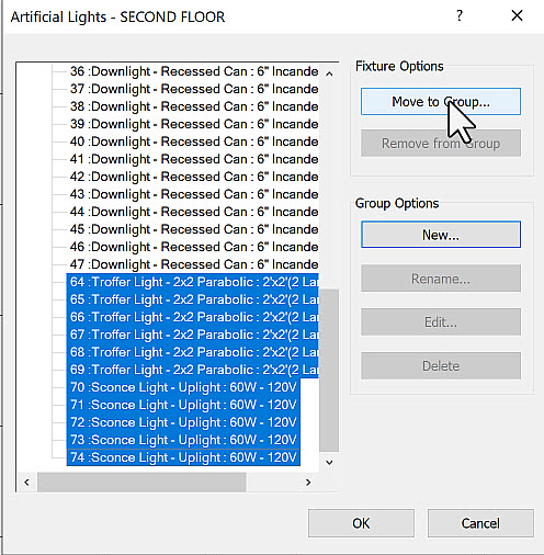
- In the Artificial Lights dialog box, select New under Group Options and name the group Second Floor Breakroom.
- Scroll down to the bottom of the light list and select all the Troffer Lights and all the Sconce Lights.
- Click Move to Group… and select the Second Floor Breakroom group.
- Scroll to the top of the list and note that the selected lights are now all listed under the Second Floor Breakroom group.
- Click OK to close the Artificial Lights dialog box.
- Save the file.