& Construction

Integrated BIM tools, including Revit, AutoCAD, and Civil 3D
& Manufacturing

Professional CAD/CAM tools built on Inventor and AutoCAD
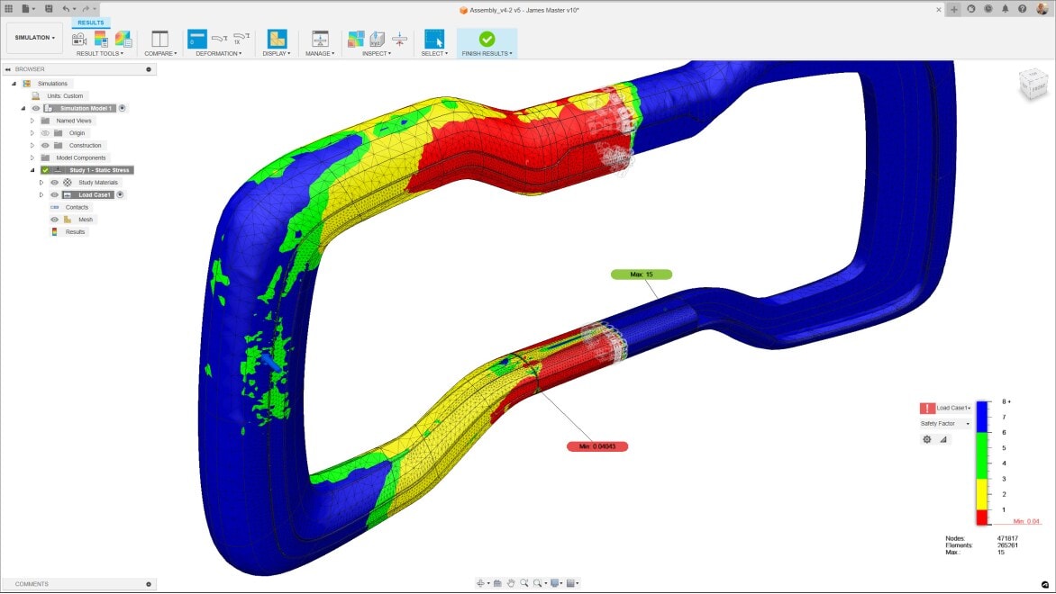
Finite element analysis (FEA) is a computerized method used to predict how a product reacts to real-world forces such as stress, vibration, heat, and fluid flow. It helps engineers and manufacturers understand whether a product will break, wear out, or function as designed. FEA plays an important role in engineering, manufacturing, and product development by simulating how a product will perform under real-world conditions, while maintaining safety and efficiency requirements.
Finite element analysis software breaks down a complex object or system into smaller, simpler parts called finite elements. These elements are connected at specific points known as nodes. Using mathematical equations, FEA software simulates how each small element behaves under various physical forces such as stress, heat, vibration, and fluid flow. This process allows engineers to approximate the behavior of the entire object by analyzing the collection of individual elements.
The workflow begins with creating a detailed 3D model which is then subdivided into a mesh of finite elements in a process called meshing. Material properties, loads, and boundary conditions are applied to the model to simulate real-world conditions. The software then solves complex mathematical equations—numerical approximations of physical laws—for each element iteratively.
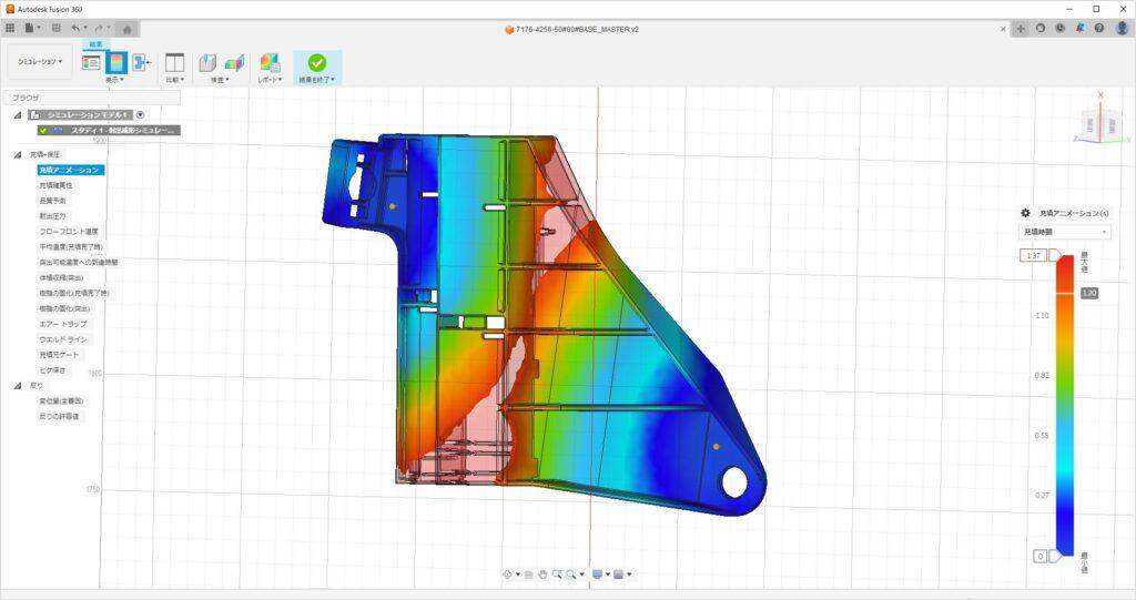
Compared to manual calculations, FEA software can handle far more complex geometries, multiple physics effects simultaneously, and large-scale problems quickly and accurately. It accurately predicts how products respond to various physical effects. These include mechanical stress, vibration, fatigue, motion, heat transfer, fluid flow, electrostatics, and processes like plastic injection molding.
The final FEA results are analyzed by engineers to guide design improvements, enhance safety, and performance. This leads to a reduction in development time, costs, and risks while increasing product reliability.
Finite element analysis (FEA) software allows engineers to accurately model product performance, prototype virtually, use predictive data for improved simulations, and reduce development time and costs while enhancing safety and reliability.
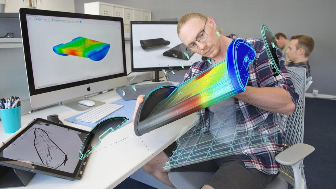
Finite element analysis (FEA) software closes the gap between your 3D design and the real world. When you can apply forces like heat, mechanical stress, and vibration computationally to your digital model, its performance in the real world can be modeled with a deep level of accuracy.
Virtual prototyping helps engineers identify and address performance weaknesses early, improving designs without the need for costly physical prototypes.
FEA software supports predictive analysis by incorporating historical data, giving engineers better starting points for simulations and improving the reliability of results.
By simulating real-world conditions digitally, FEA reduces development time, lowers costs, minimizes physical testing, and helps accelerate product development cycles.
Computational fluid dynamics simulation and solid body motion analysis software. Available as CFD Premium and CFD Ultimate
Powerful product design and engineering tools for 3D mechanical design, simulation, visualization, and documentation.
Get Inventor + AutoCAD + Autodesk Fusion + more—Professional-grade tools for product development and manufacturing planning.
— Koichi Sato, Kawai Plastics
Image courtesy of Dynamic Structures Ltd.
See how the Autodesk solution for FEA and digital prototyping is helping manufacturers design, visualize, and simulate consumer products, industrial machinery, building products, and more.
Finite element analysis (FEA) is used across industries like automotive, aerospace, civil engineering, and electronics. It's used to simulate and optimize structural stress, vibration, heat transfer, and fluid flow, enabling safer, more efficient, and innovative product designs.
FEA is used in industries like automotive and aerospace to predict where parts might fail due to stress. Engineers are able to redesign components to withstand real-world forces and improve safety.
Machinery and structural engineers apply FEA to study vibrations in equipment and buildings to prevent resonant frequencies that could cause damage or reduce lifespan.
FEA simulates thermal behavior in products such as electronic devices and engines, helping optimize cooling designs and prevent overheating during operation.
In naval and aerospace industries, FEA models fluid flow around structures like ship hulls or aircraft wings to improve efficiency and reduce drag under various operating conditions.
Autodesk is committed to helping educate tomorrow's leaders. Get free access to our entire portfolio of products with the Autodesk Education plan.
Alexander Hrennikoff (1941) and Richard Courant (1943) introduced mesh discretization methods.
The finite element method (FEM) was formalized in the 1950s by Ray Clough and colleagues. This lead to practical applications in structural engineering and the introduction of the term "finite element" in 1960.
Major growth occurred in the 1960s and 1970s, with the development of the first FEA software.
Universities and industries expanded FEA to civil, aerospace, mechanical, and electrical engineering.
Key mathematical breakthroughs and wider use of mainframe computers enabled complex simulations and commercial FEA tools to become more popular.
FEA saw advances for large-scale, multi-physics, and industry-wide applications in the 1990s and 2000s.
The integration of FEA into engineering workflows, with validation standards and cloud-based solutions, became prominent.
The 2010s and 2020s introduced simulation governance, technical requirements, and scalable online platforms, making FEA indispensable to engineering design across all sectors.
Discover the value of simulation software in design and engineering, its applications across industries, and how Autodesk Nastran and Autodesk Fusion provide powerful tools for optimizing product design and manufacturing.
This guide highlights important tools to understand and best practices as you get up to speed with simulation in Autodesk Fusion.
Fusion provides powerful FEA and simulation tools for mechanical engineers to precisely validate and optimize designs.
Learn more about how finite element analysis (FEA) enhances product design, safety, and cost-efficiency and how Autodesk solutions can help.
FEA software takes your 3D design file and tests its performance against the fluid dynamics, heat transfer, mechanical stress, and other factors it will be exposed to when it exists in the real world.
Finite element method (FEM) is the solving of equations generated by the mathematical modeling of engineering projects.
Finite element analysis (FEA) is the application of finite element method (FEM) data, which interprets its mathematical values. It analyzes how you can improve the performance of your model when exposed to various physical forces.
You can absolutely do FEA by hand. Finite element analysis (FEA) is just math. In the pre-digital age, performance calculations were done on paper using a physical prototype during testing.
The difference today is that the algorithms driving simulation software can perform FEA calculations faster and can test for multiple force effects simultaneously.
It also means you don’t need to build a physical model to apply calculations—the system can apply them to your 3D design without leaving your desktop.
While FEA by hand is still feasible for simple geometries or when a prototype exists, FEA simulation software can test the performance of ever-more complicated geometries. The design process isn’t constrained by what you can measure by hand.
The ability to solve many simulations using secured cloud solving does free up personal system resources such as RAM, however, for the software that also has the ability to solve simulations locally (such as Moldflow and CFD), the installation guides provide test cases to recommended RAM and other resources for the installation to run efficiently. Here is a breakdown for the current releases of Autodesk simulation software:
Simulation software is quite workstation intensive. A general rule of thumb is that you need around 16 GB of RAM per million degrees of freedom in a standalone system, but this can vary greatly based on model complexity.
The ability to solve many simulations using secured cloud solving does free up personal system resources such as RAM, however, for the software that also has the ability to solve simulations locally (such as Moldflow and CFD), the installation guides provide test cases to recommended RAM and other resources for the installation to run efficiently. Here is a breakdown for the current releases of Autodesk simulation software:
The main steps involved in setting up an FEA model include:
Following these steps ensures a structured approach to achieving accurate and meaningful FEA simulations.
Interpreting simulation results involves:
Finite Element Analysis (FEA) is essential in engineering and product design because it enables engineers to accurately predict the behavior of structures and components under various physical conditions. This helps identify potential design flaws, optimize performance, enhance safety, reduce the need for costly physical prototypes, and accelerate the overall development process.
Optimizing product design using FEA involves several steps:
1. Defining clear objectives and constraints.
2. Creating detailed 3D models with accurate material properties.
3. Applying realistic boundary conditions and loads.
Simulations are then run to identify areas of high stress or inefficiency, guiding iterative refinements such as:
This process ultimately improves product performance, reduces material usage, and lowers costs.
Finite Element Analysis (FEA) can address a wide range of engineering problems, including:
These broad capabilities make FEA an essential tool for designing safer, more efficient, and optimized products across various industries.
Free Autodesk software and/or cloud-based services are subject to acceptance of and compliance with the terms and conditions of the terms of use and/or other terms that accompany such software or cloud-based services. Software and cloud-based services subject to an Educational license or subscription may be used by eligible users solely for Educational Purposes and shall not be used for commercial, professional or any other for-profit purposes.


