& Construction

Integrated BIM tools, including Revit, AutoCAD, and Civil 3D
& Manufacturing

Professional CAD/CAM tools built on Inventor and AutoCAD
Electrical drawings, also known as electrical plans, are technical documents that depict and notate designs for electrical systems. Workers use these documents to install systems on-site. In electrical drawings, every type of component and connection has its own specialized symbol and every detail matters.
AutoCAD can be used as a fully-featured electrical drawing program, with most of its electrical capabilities available through the dedicated Electrical toolset, which is included with a subscription to AutoCAD. This powerful toolset allows you to efficiently create, modify, and document electrical control systems with ease. Gain access to extensive libraries of symbols, automated drafting features, and real-time error checking to streamline your workflow and enhance productivity.
An electrical drawing is intended to provide a visual representation of the layout of an electrical system, including the components and the connections between them. There are various kinds of electrical drawings with different purposes, but generally you can begin the process by sketching out the layout of the electrical system, using either quality paper and a pencil, or electrical drawing software such as AutoCAD Electrical. Include all components, represented by special symbols. Then, you add lines to connect the components, representing wires. Labels and other annotations can be added to provide further information and clarification for the reader.
2D and 3D CAD tools, with enhanced insights, AI-automations, and collaboration features. Subscription includes AutoCAD on desktop, web, mobile, and seven specialized toolsets.
Best-in-class tool for 2D CAD drafting, drawing, and documentation. Subscription includes AutoCAD LT on desktop, web, and mobile.
While electrical drawings have long been created by hand, using electrical drawing software has many benefits, including:
It’s far faster to place and connect pre-made electrical component symbols and wiring digitally rather than drawing them by hand. Many other elements are also automated, giving you more time to focus on the things that matter.
Using electrical drawing software like AutoCAD can help to eliminate costly and unfortunate mistakes by dramatically reducing the risk of human error when creating electrical layout drawings.
Once you’ve created a set of electrical plans using AutoCAD’s Electrical Toolset, you can easily share it with other members of your team instantaneously.
Learn the symbols used to notate components in an electrical plan.
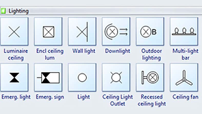
Use AutoCAD tools to diagram lighting sources, from klieg lights to sconces.
From single-pole to multiple-pole, AutoCAD can help you diagram electrical circuits.
Fuses limit the flow of current to prevent damage to other components. With AutoCAD, fuses are easier to design and diagram.
Electrical circuits must connect to the ground to maintain safety. Learn the correct ways to diagram electrical grounds with AutoCAD’s electrical layout drawing tools.
Wires connect components, and AutoCAD gives you the design power to specify what you need.
AutoCAD gives you the electrical plan design tools to diagram resistors, which reduce current flow, adjust signal levels, divide voltages, and more.
Capacitors store potential energy; they're polarized or nonpolarized. The AutoCAD Electrical toolset enables you to diagram capacitors correctly.
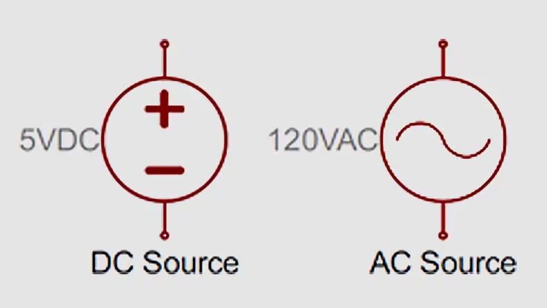
From DC to AC currents and batteries, there are many ways to power what you make. AutoCAD makes the electrical drawing planning and design process easy.
There are four main types of electrical drawings:
A schematic diagram is the simplest version of an electrical drawing, and aims to convey the functionality and connectivity of a circuit using lines and universal symbols.
These are used to depict more accurately the reality of an electrical system, rather than just the logic underpinning it. They include details about how the wires and components are arranged, and often what wire colours are used.
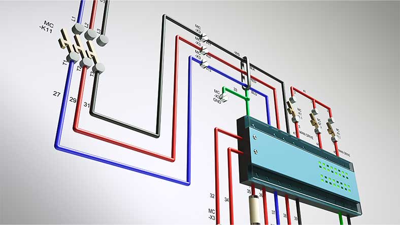
This type of electrical plan is even more detailed, using pictures to depict components and including details of how wires are attached.
Block diagrams use blocks and lines to illustrate the relationship between components.
Many different professions and industries use electrical drawing programs such as AutoCAD in their everyday activities or for project work. Electricians use electrical plans in installation and maintenance, during both planning and implementation. Electrical engineers design elaborate systems and work towards ensuring compliance with regulations using electrical drawing software. Product designers often use it to determine how to make something work or to find the most efficient way to carry out an electrical function, while electronics technicians may use electrical drawing software extensively in troubleshooting.
Learn the basics of the AutoCAD interface and how to open essential tools.
From basic schematic design to advanced file management, these resources can get you up to speed so you’re ready to handle electrical layout drawing.
Get step-by-step instructions on circuit and wiring design, report generation, and a host of topics related to electrical drawings.
Martz Technologies switched from AutoCAD LT to AutoCAD (with the Electrical toolset) and saw greater efficiency with the additional features for electrical plans.
Martin CSI relies on the AutoCAD Electrical toolset for industrial manufacturing projects—including an ice cream sandwich filler machine.
CLE streamlines its manufacturing processes to deliver consumer products onto store shelves.
Explore the possibilities of AutoCAD electrical drawing software with these learning sessions, tips, and workflows.
Learn your way around the electrical drawing software interface.
Learn more about the AutoCAD Electrical toolset, including AI enhancements and features specific to electricians and electrical designers.
In this Autodesk University on-demand video, explore AutoCAD's AI-driven tools for intelligent object recognition, predictive analytics, and seamless collaboration across AutoCAD toolsets.
In this on-demand class, discover how linked drawings and components update automatically, improving efficiency and design quality. Learn how to access symbol libraries, create custom drawing types, link components, and generate reports based on drawing types.
Get answers to popular questions about AutoCAD software licenses and subscriptions, and see what’s possible with Autodesk electrical drawing software.
Discover how AutoCAD Electrical can significantly improve your documentation process, save 25% more time, and allow you to run audits and extract critical data like BOMs and wire reports.
This can vary, but electrical plans are often made on the same scale as the associated floor plans, frequently 1:50.
Yes, we offer a range of free file viewers, which others who don’t have the same electrical drawing software can use to view your drawings. You can find detailed information about sharing files and collaborating with team members in our online tutorial.
Yes, we offer free trials of AutoCAD electrical drawing software, so you can try it out without any risk.
A schematic shows the logic behind an electrical circuit, how different components are connected and the behavior of the circuit, but it doesn’t include precise details about the exact physical layout of the wires. A circuit diagram shows the specifics of how and where components are connected, including wire colors. The former type of electrical drawing is a broad blueprint used for design and troubleshooting, while the latter is a practical document used in wiring, installation and maintenance.
Electrical drawings are typically read from left to right or from top to bottom. To understand what is depicted, you need to familiarize yourself with what each of the component symbols refers to. You also need to identify which direction the current flows by looking at the lines on the electrical plan.

