Setting 2D flood types
Assign 2D flood types to nodes in a 2D zone in order to couple them to the 1D sewer network.
Tutorial resources
These downloadable resources will be used to complete this tutorial:
Step-by-step guide
2D nodes are used in 2D simulations to model the exchange of water between the 1D sewer system and a 2D zone. When modelling the 1D-2D surface interaction, node ground levels can vary greatly from ground model data, resulting in inaccurate flows and instability. Node ground levels, element ground levels, or node locations may need to be changed. In this example, one potential solution is tried. Always consider what is most appropriate for the specific model and its purpose.
- For this example, open the transportable database Set_2D_Fld_Types.icmt, and then copy it to the database.
- In the Database, double-click 1D/2D Sewer Model to open it on the GeoPlan.
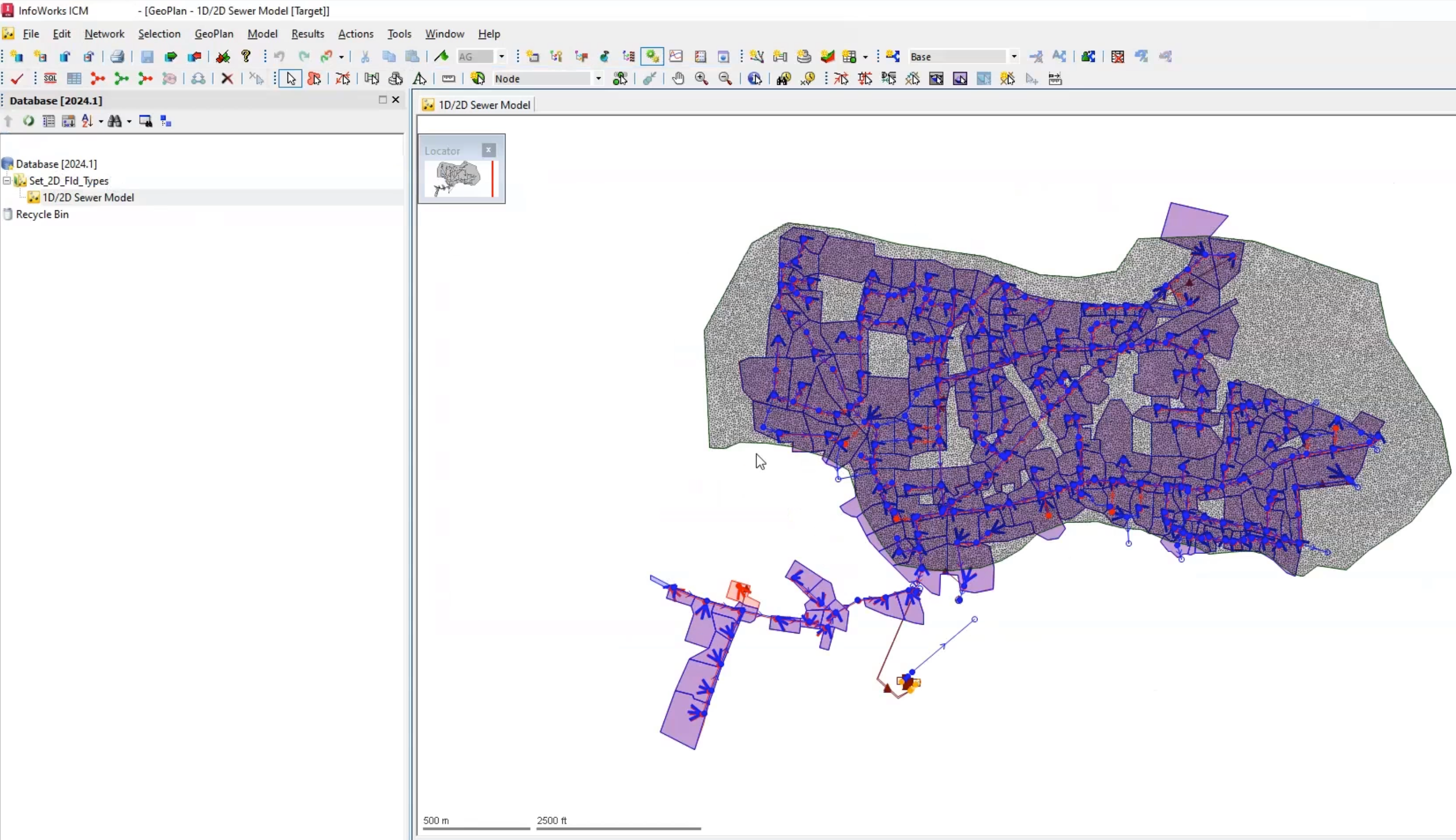
The 2D zone is already imported and a 2D mesh is generated. Now, couple the 1D sewer network by setting 2D flood types:
- In the GeoPlan, select the 2D zone.
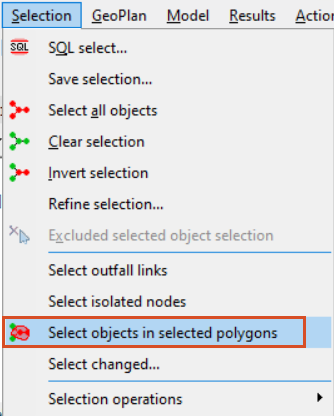
- From the Selection menu, click Select objects in selected polygons to select everything within the 2D zone.
- While pressing the CTRL key, from the Windows toolbar, expand the Grid windows drop-down and select New nodes window.
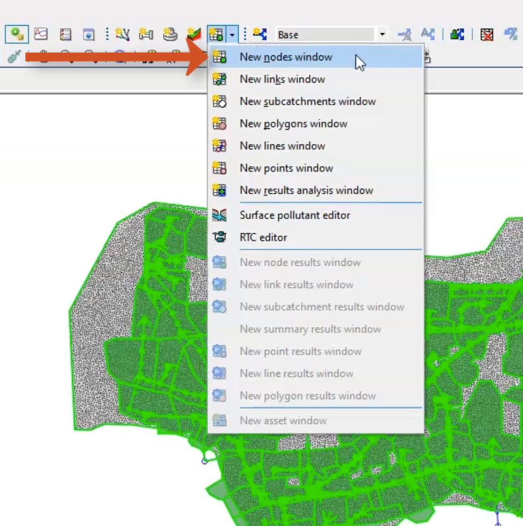
This grid now displays all nodes within the 2D zone.
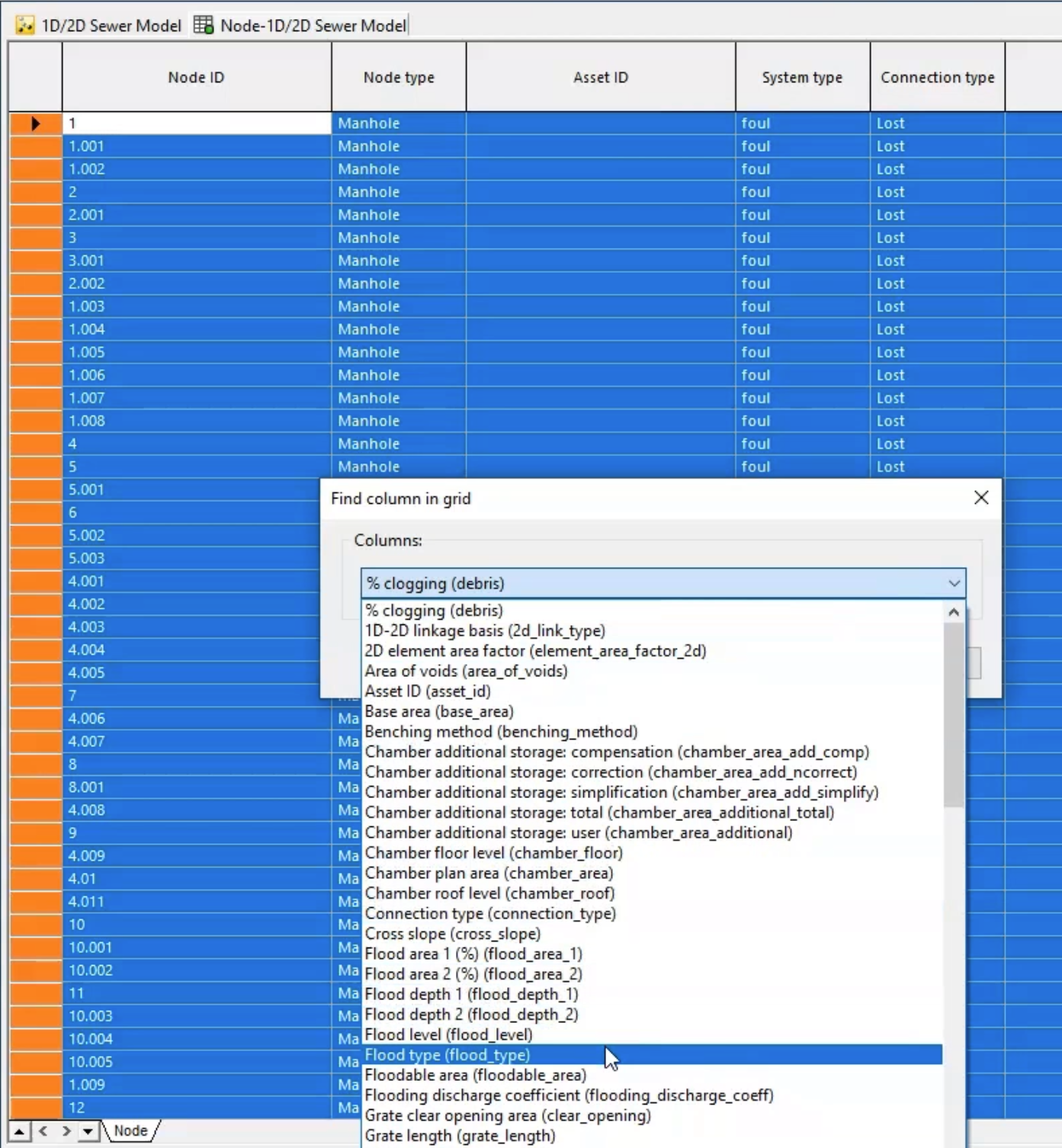
Next, locate the Flood type column:
- Right-click the grid and select Find column.
- In the Find column grid dialog box, expand the Columns drop-down, and select Flood type.
- Right-click the Flood type column heading and select Sort on selected columns descending.
- While pressing the SHIFT key, select all fields with a value of Stored.
- Right-click the selection and select Current cell(s) value > Set new value(s) for cell(s).
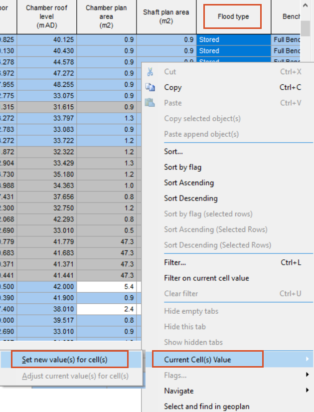
- In the New Cell Value popup, select 2D.
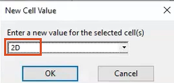
- Click OK.
For a 2D flood type, the exchange of water between the 2D manhole and the mesh is calculated using the weir equation, assuming a weir crest level at the node ground level and crest length equal to the node shaft circumference.
- In the nodes grid window, find or scroll to the Flooding discharge coefficient column.
A flooding discharge coefficient equivalent to the weir discharge coefficient is specified for the node.
- Ensure that the rows have a default value of 0.5. If not, populate the values.
The next step is to assign the Gully 2D flood type to the nodes which are currently set as Lost. First, however, the head-discharge relationship that these nodes will follow needs to be defined:
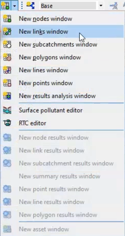
- From the Grid windows drop-down, select New links window.
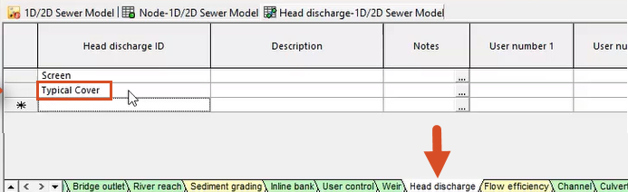
- At the bottom of the grid window, scroll to the Head discharge tab. This is currently populated with a screen head discharge table.
- In the Head discharge ID column, select the cell below Screen.
- Enter an ID of “Typical Cover” to generate a new table entry.
- In the far-left cell of the same row, double-click to open the table Properties window.
- In the Head discharge power table field, click More (…).
In the Head discharge window, enter the following values into the table:
- In Row 1, set the Head to -0.5 and the Discharge to -2.
- In Row 2, set the Head to 0 and the Discharge to 0.
- In Row 3, set the Head to 0.5 and the Discharge to .001.
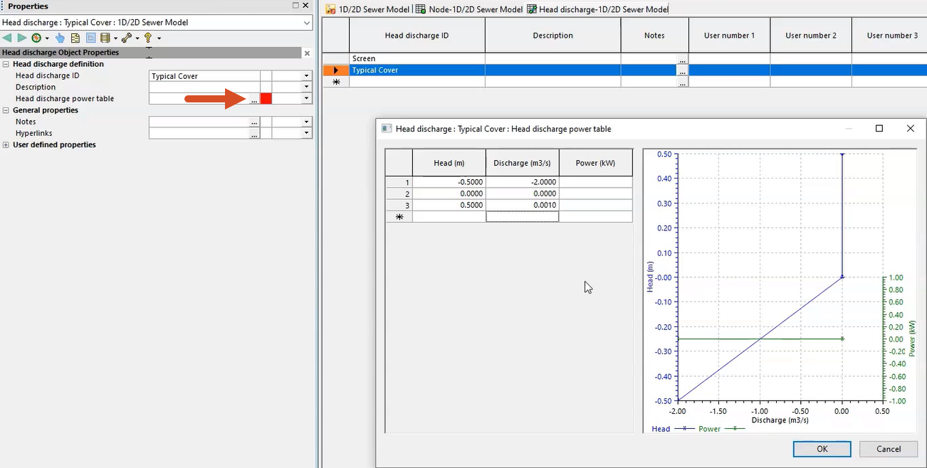
Negative values in this table represent flooding onto the 2D zone, and positive values represent flow entering the sewer system. This table has been set up to allow minimal flow into the node from the surface, while allowing a relatively free discharge of flow (flooding) onto it. This would be most appropriate for foul or sanitary sewers, or where the gully connections are represented in detail.
- Click OK.
Now, assign the 2D Gully flood type to nodes currently set as Lost:
- Return to the nodes grid window.
- In the Flood type column, use the SHIFT key to select all fields with a value of Lost.
- Right-click the selections and select Current cell(s) value > Set new value(s) for cell(s).
- In the New Cell Value popup, select Gully 2D.
- Click OK.
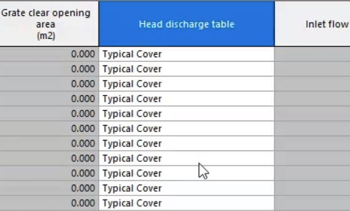
For a gully 2D flood type, the exchange of water between the 2D manhole and the mesh is calculated using a head discharge relationship.
- Scroll to the Head discharge table column, which should be populated with the Typical Cover table that was just created.
Finally, update the outfall nodes:
- In the nodes grid window, right-click the Node type column heading and select Sort on selected column(s) descending, so that the outfall nodes appear at the top of the list.
- Select the Outfall values.
- Right-click the selection and click Current cell(s) value > Set new value(s) for cell(s).
- In the New Cell Value popup, select Outfall 2D.
- Click OK.
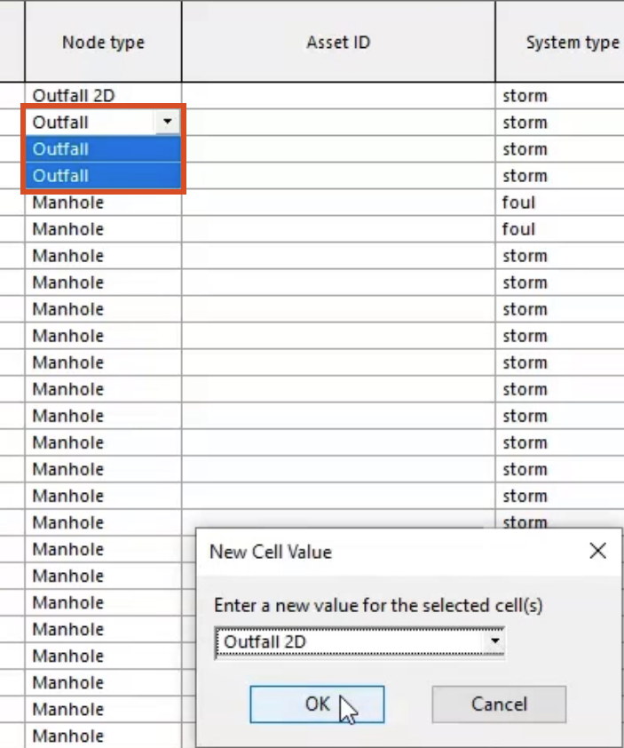
The 2D outfall is used to allow the exchange of water between an outfall and a 2D element. These outfalls will now interact with the 2D mesh, rather than the flow being lost from the system.
- Click Validate to make sure there are no errors in the network.
- Click OK.
- Click Commit changes to database to save the changes.
- Add a comment, such as "Added connections for 1D nodes to 2D".
- Click OK.