Applying rainfall to a 1D-2D integrated sewer model
Set up the 2D mesh and rainfall in preparation for coupling a 1D-2D sewer model.
Tutorial resources
These downloadable resources will be used to complete this tutorial:
Step-by-step guide
Rainfall profiles and their corresponding evaporation profiles can be applied directly to the elements in a 2D mesh. Rainfall applied to the 2D mesh and rainfall applied to subcatchments can also be separated. In this example, set up options to apply rainfall to the 2D zone outside of subcatchments.
To begin, open the database, and then open the desired .icmt file and ground model:
- In this example, from the File menu, select Open > Open transportable database.
- Navigate to the downloaded example files folder, and select App_Rain_2D_Mesh.icmt.
- Click Open.
- In the popup about opening the database as read-only, click Yes.
- In the transportable database window, right-click the top-level folder and select Copy.
- In the popup, click Continue.
- Right-click the Database and select Paste (with children).
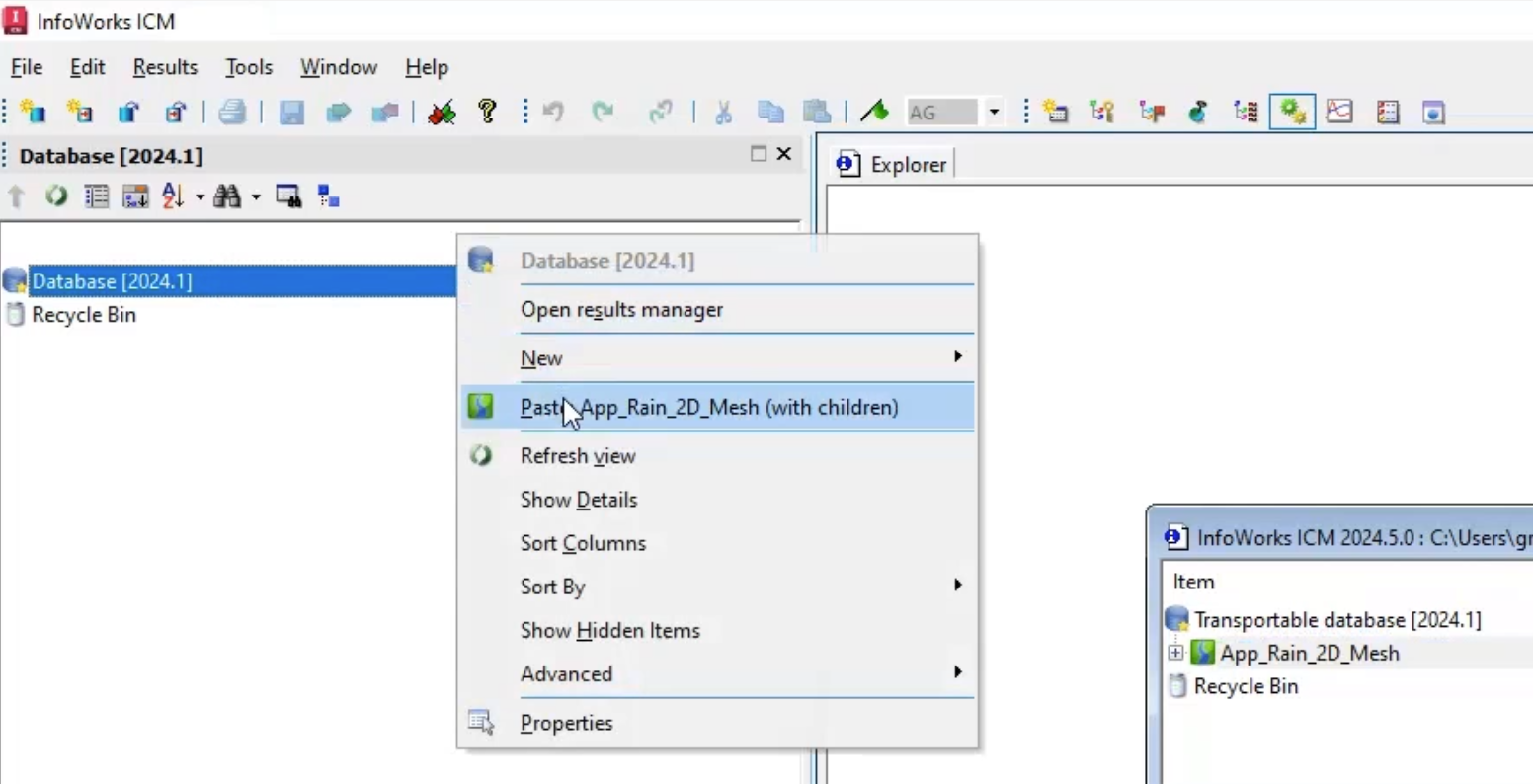
- In the Copying popup, enable Copy ground models.
- Click Continue.
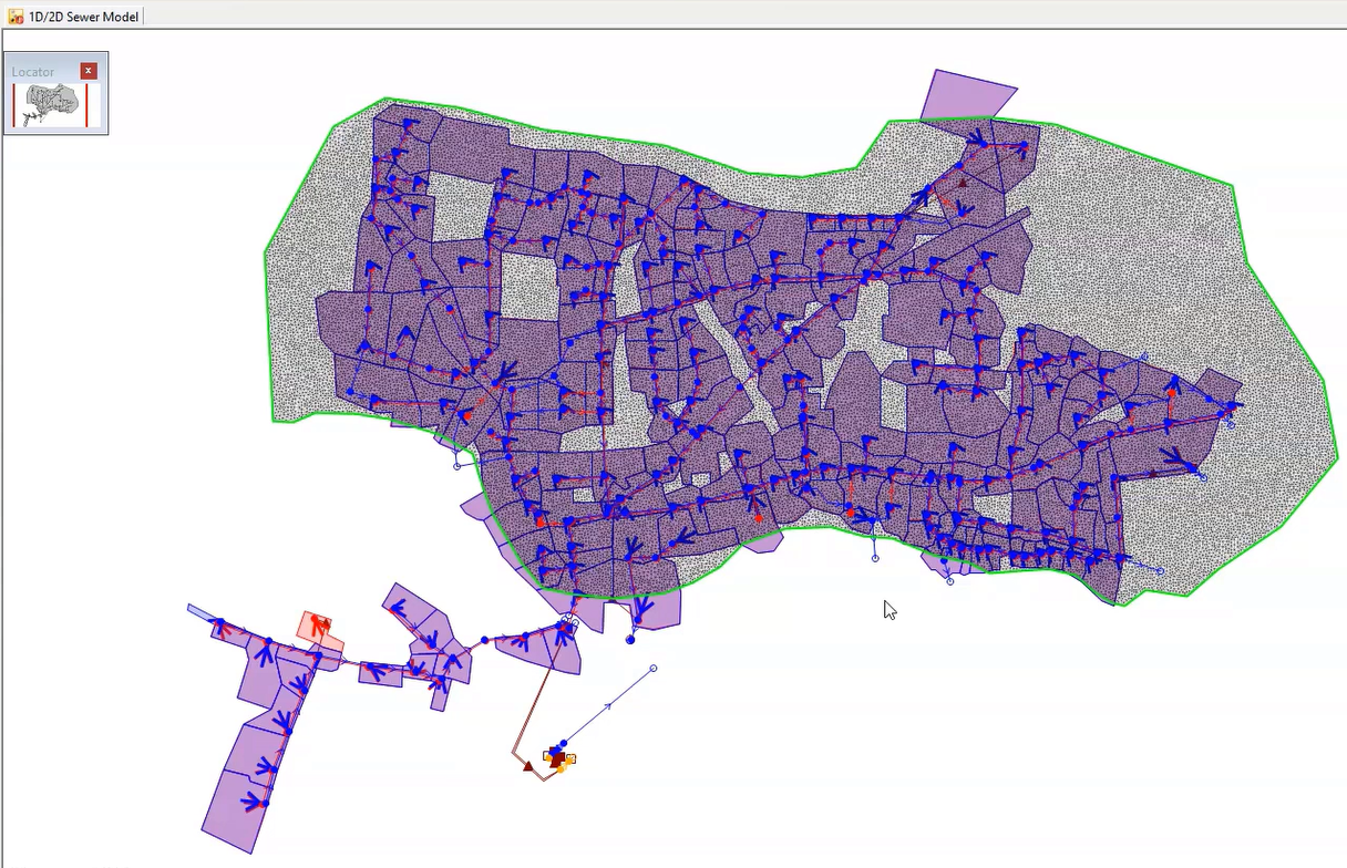
- In the Model Group, double-click 1D/2D Sewer Model to open it on the GeoPlan.
To import the pre-defined 2D zone:
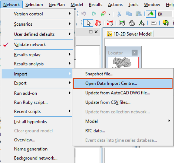
- From the Network menu, click Import > Open Data Import Centre.
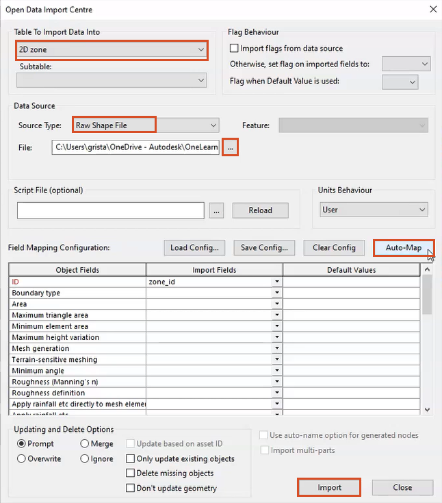
- In the ODIC, Table To Import Data Into drop-down, select 2D zone.
- Under Data Source, ensure the Source Type is set to Raw Shape File.
- Click More (…).
- Navigate to the example files for this tutorial, and select 2D Zone.shp.
- Click Open.
- Under Field Mapping Configuration, click Auto-Map to search the import file for fields that match those that define the nodes in the network.
- Click Import.
- In the notification popup, click OK.
- Close the ODIC.
The 2D zone is imported into the model.
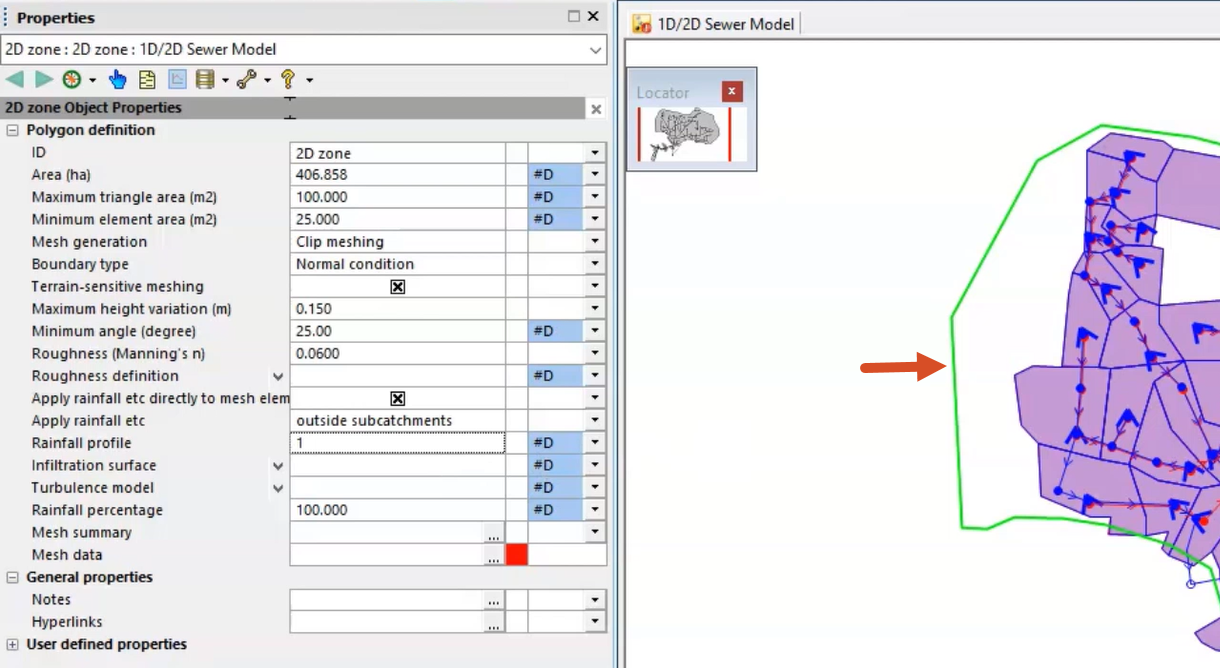
- Using the Select tool, double-click the 2D zone to open the Properties window.
Adjust the following 2D zone settings:
- Set the Mesh generation to Clip meshing.
- Set the Boundary points to Normal condition.
- Enable Terrain-sensitive meshing.
- Set the Maximum height variation to 0.15.
- Set the Roughness (Manning's n) to 0.06.
- Enable Apply rainfall etc directly to mesh.
- Set the Apply rainfall etc drop-down to outside subcatchments.
If 2D meshes and subcatchments overlap, the default is for rainfall to be applied to both subcatchment and 2D elements independently. Selecting outside subcatchments prevents applying rainfall twice by restricting the rainfall to elements with centroids outside of subcatchment boundaries.
By default, and in this example, the Infiltration surface field is set to a blank value. With no infiltration applied, 100% of the rainfall is converted to runoff.
The Rainfall percentage value is also set to 100% by default. This value can be used as a pro-rata adjustment to the rainfall across the entire 2D zone. Adjusting this field could be used instead of simply applying rainfall outside of subcatchments. For example, a scaled-down rainfall of 10-20% might be applied to the mesh elements within subcatchments for an urban area.
With the 2D zone parameters set, the mesh can be generated:
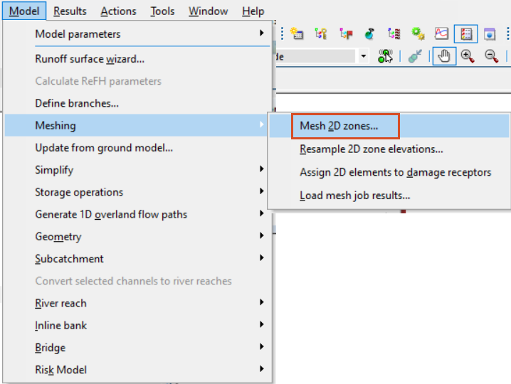
- Make sure that the 2D zone is still selected on the GeoPlan.
- From the Model menu, select Meshing > Mesh 2D zones. Note that from version 2024.5 onwards, CTRL+M can also be used.
- In the Mesh 2D Zones dialog box, ensure that Voids, Break lines, and Walls are set to None.
- From the Database, drag the 2m DTM ground model into the Mesh 2D Zones dialog box and drop it into the Ground Model group box.
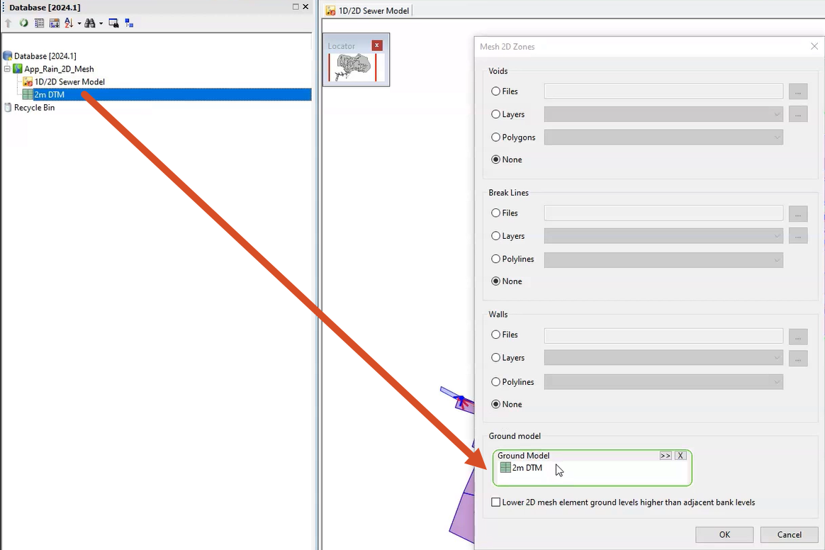
- Click OK to mesh the 2D zone.
- In the Schedule Job(s) popup, click OK.
- From the Window menu, select Job control window to display the status of the mesh job and some information on the generation.
Once the mesh has completed, it can be loaded into the model.
- From the Job Control window, click the Mesh ready status.

- In the Manage mesh results dialog box, click Load mesh.
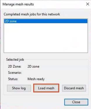
- Click Close.
The mesh is generated and added to the 2D zone: