Adding breaklines
Force triangle edges along a given line and ensure accurate ground model levels by adding breaklines.
Step-by-step guide
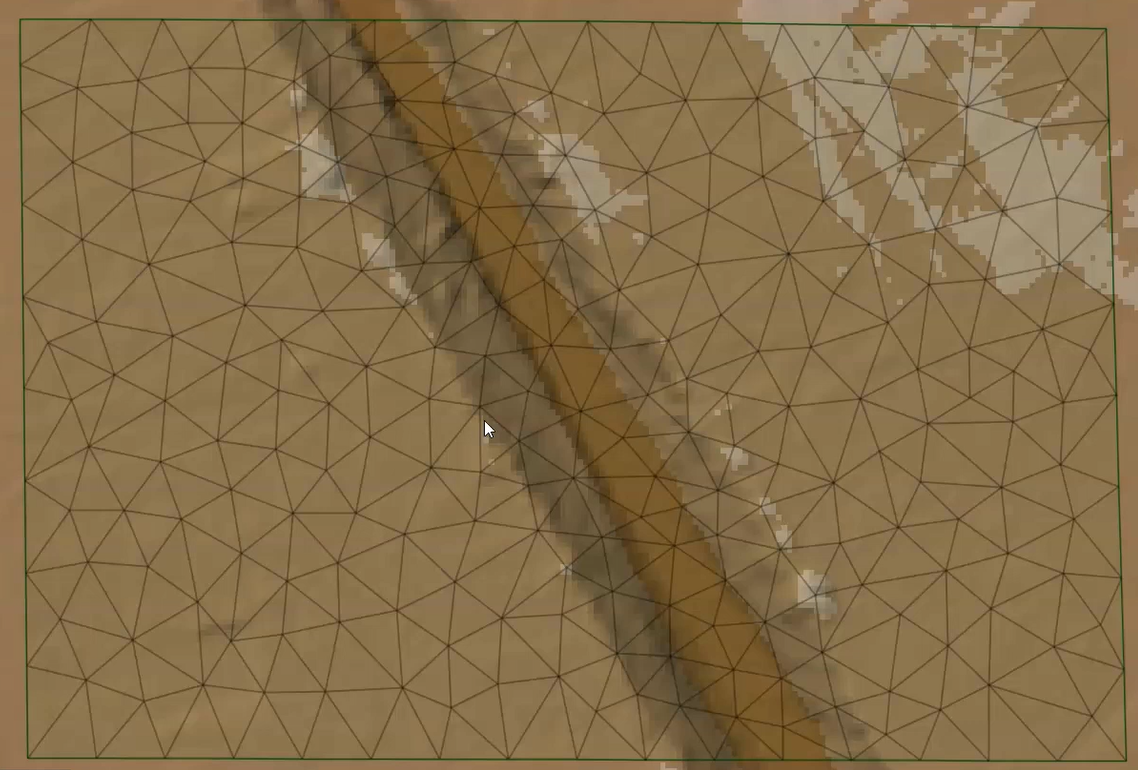
Breaklines are used to force triangle edges along a given line. These can be used to enhance the detail of the mesh, or to ensure that the ground model topography is represented more accurately by the mesh.
Breaklines can help pick out the tops of embankments or the bottom of channels. In this example, a mesh has already been generated using the default parameters.
Open a 3D view to compare the 2D mesh to the underlying ground model:
- From the toolbar, click New 3D network window.
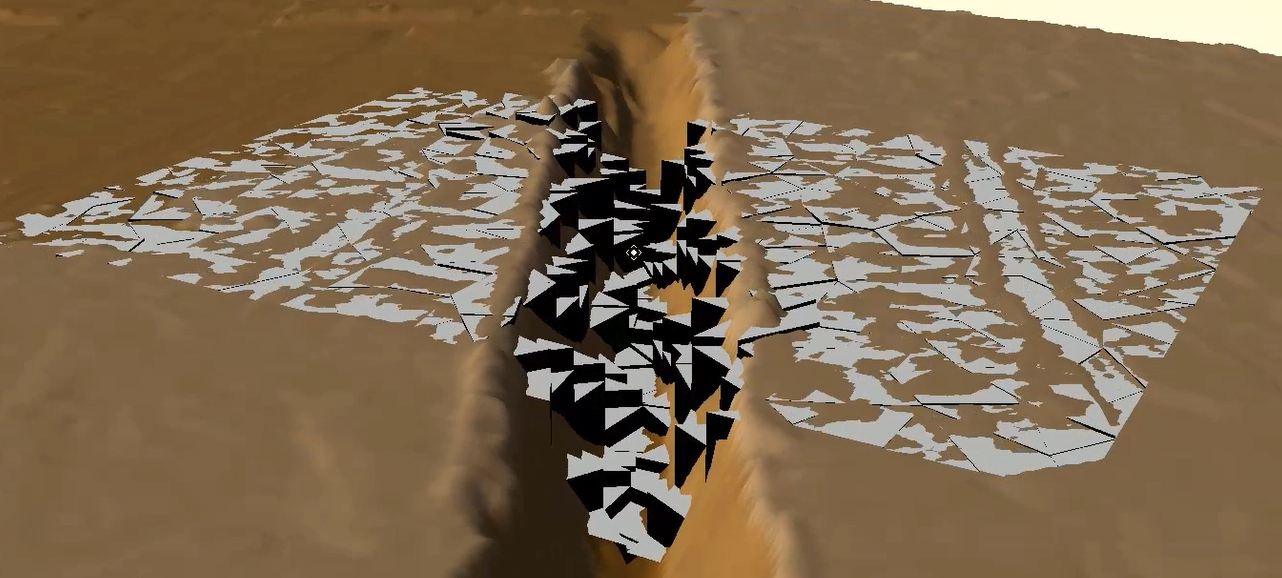
Because elements have a single level applied, breaklines can be used here to help create a more representative mesh by forcing how the elements are created.
Start by creating a new scenario:
- From the Scenarios toolbar, click Create scenario.
- Add a New Scenario Name of Breaklines.
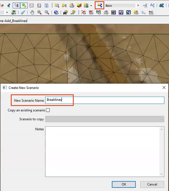
- Click OK.
Now, add some General line objects to help pick out the topography more accurately. For this example, add a pair of general lines at the top and bottom of the channel to help with the mesh creation:
- From the GeoPlan Tools toolbar, expand the New Object Type combo box, and select Line.
- Click New Object.
- Along the outer edge of the embankment, click to draw the start and end points of the first line.
- In the New Line dialog box, set the Category to Breakline.
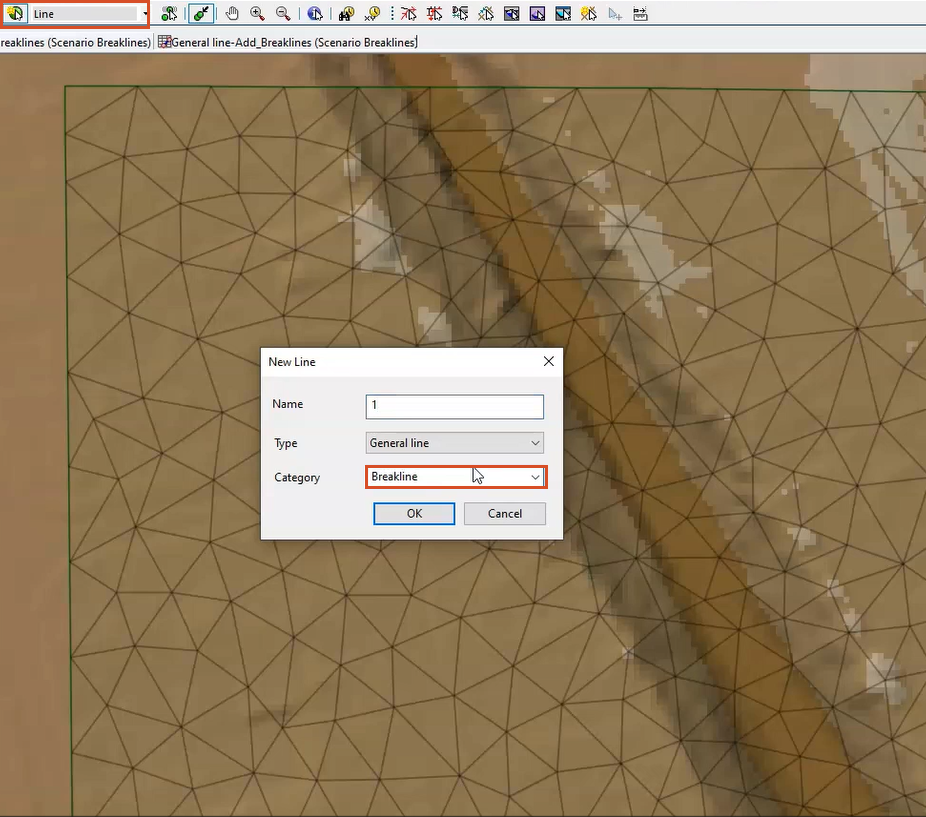
When creating only a few lines, the category can be assigned manually. However, if importing numerous breaklines, either set the category during the import process or update the category in the line grid window.
- Repeat steps 6-8 to add three more lines—on the bottom edges of the channel and the opposite edge of the embankment—assigning each the Breakline category.

With all breaklines added as general line objects and assigned the same category, re-mesh the 2D zone:
- From the Model menu, select Meshing > Mesh 2D zones.
- In the Mesh 2D Zones dialog box, under Break Lines, select Polylines.
- Expand the drop-down and select Breakline.

- Click OK to mesh the 2D zone.
- In the Schedule Job(s) popup, click OK.
- In the Job Control window, under Status, click Mesh ready.
- In the Manage mesh results dialog box, click Load mesh.
- Click Close.
The breakline is used to determine the boundary of the adjacent mesh elements, and the mesh lines up with the breaklines.
For a better understanding of the impact the breaklines have on 2D element levels, view the results in 3D:
- From the Windows toolbar, click New 3D network window again.

The bottom and top of the channel are now more accurately represented, which leads to more accurate results.