• InfoDrainage

Accessing object properties

Access the properties for manholes, pipes, and catchments.


Tutorial resources

These downloadable resources will be used to complete this tutorial:


00:03

you can access the specific properties for individual drainage system,

00:07

objects to look at them in further detail.

00:10

Zoom in on the object. You want to view the data for such as, one

00:16

ensure the select tool is active and then double click manhole one.

00:22

The manhole one dialog box opens which contains all the object properties

00:26

for this manhole including its type east ING's in northern location,

00:31

data,

00:32

cover level

00:33

and diameter.

00:35

The cover level has been derived from the surface information

00:39

but notice that it's invert level is set to 0.00 because the

00:43

pipe invert levels in manhole chamber floors have not yet been designed.

00:48

Click the inlets tab

00:51

here, you can see the catchment one is the only inlet assigned to it right now,

00:56

click the outlets tab

00:58

here, you can see that pipe one is assigned as the only outlet,

01:03

Click cancel to close the manhole one. dialogue

01:07

Now, double click on Pipe one.

01:10

The connections table appears.

01:12

Notice that all the pipes are listed not just the pipe you double clicked,

01:17

however,

01:18

the pipe you selected is highlighted in the table.

01:21

The table provides information about the pipe, such as its length,

01:25

connection type slope diameter and more

01:31

At this point.

01:32

The downstream and upstream invert levels are also set to zero

01:37

click cancel.

01:39

Double click the catchment area. One icon

01:43

like the manhole. The dialog box for this particular catchment area opens

01:47

with the runoff tab, active

01:50

again because the system is not complete.

01:53

These values may not be accurate.

01:55

Just be aware that this is where you can access this data

Video transcript

00:03

you can access the specific properties for individual drainage system,

00:07

objects to look at them in further detail.

00:10

Zoom in on the object. You want to view the data for such as, one

00:16

ensure the select tool is active and then double click manhole one.

00:22

The manhole one dialog box opens which contains all the object properties

00:26

for this manhole including its type east ING's in northern location,

00:31

data,

00:32

cover level

00:33

and diameter.

00:35

The cover level has been derived from the surface information

00:39

but notice that it's invert level is set to 0.00 because the

00:43

pipe invert levels in manhole chamber floors have not yet been designed.

00:48

Click the inlets tab

00:51

here, you can see the catchment one is the only inlet assigned to it right now,

00:56

click the outlets tab

00:58

here, you can see that pipe one is assigned as the only outlet,

01:03

Click cancel to close the manhole one. dialogue

01:07

Now, double click on Pipe one.

01:10

The connections table appears.

01:12

Notice that all the pipes are listed not just the pipe you double clicked,

01:17

however,

01:18

the pipe you selected is highlighted in the table.

01:21

The table provides information about the pipe, such as its length,

01:25

connection type slope diameter and more

01:31

At this point.

01:32

The downstream and upstream invert levels are also set to zero

01:37

click cancel.

01:39

Double click the catchment area. One icon

01:43

like the manhole. The dialog box for this particular catchment area opens

01:47

with the runoff tab, active

01:50

again because the system is not complete.

01:53

These values may not be accurate.

01:55

Just be aware that this is where you can access this data

Step-by-step:

You can access the specific properties for individual drainage system objects to look at it in further detail.

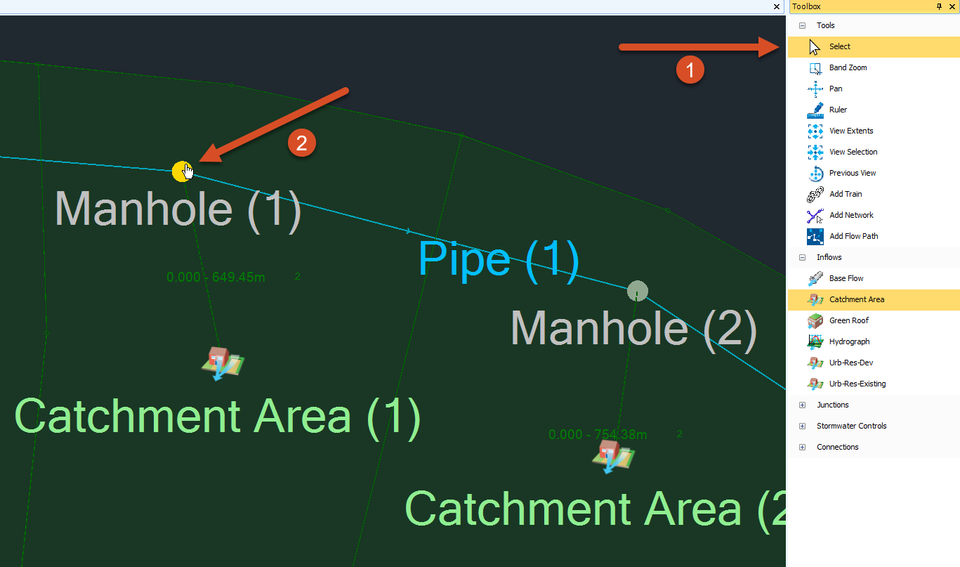
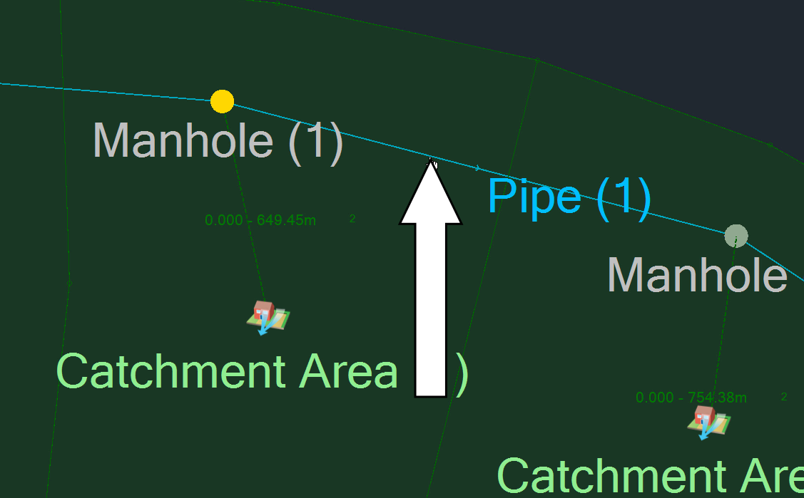
    1. In the Plan View, zoom in on the object you want to view the data for, such as Manhole (1).
    2. In the Toolbox, ensure the Select tool is active.
    3. In the Plan View, double-click Manhole (1).
      The Toolbox with Select highlighted and the Plan view with Manhole (1) selected.
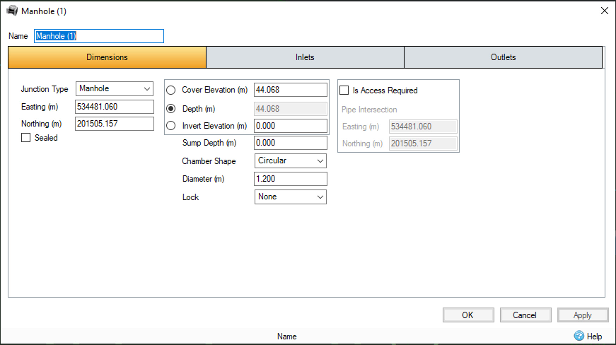
    4. The Manhole (1) dialog box opens. Review the object properties for the selected manhole.
      The Manhole (1) dialog box, Dimensions tab.
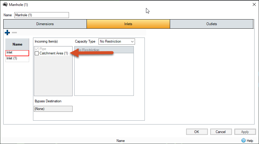
    5. Click the Inlets tab. Here, you can see that Catchment (1) is the only inlet assigned to it right now.
      The Manhole (1) dialog box, Inlets tab.
    6. Click the Outlets Here, you can see that Pipe (1) is assigned as the only outlet.
      The Manhole (1) dialog box, Outlets tab.
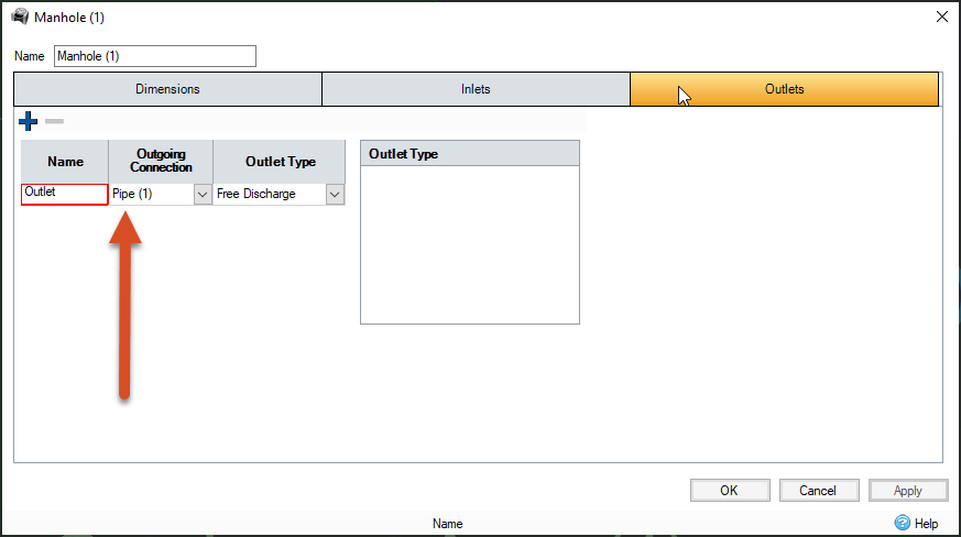
    7. Click Cancel to close the Manhole (1) dialog box.
    8. In the Plan View, double-click Pipe (1).
      The Plan view with a pipe called out as being double-clicked.
      The Connections table appears. Notice that all the pipes are listed, not just the pipe you double-clicked. However, the pipe you selected is highlighted in the table.
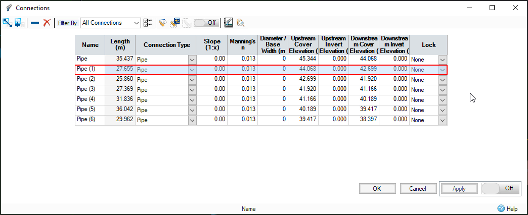
The Connections dialog box with the selected pipe highlighted.

  1. Click Cancel.
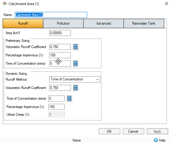
  2. In the Plan View, double-click the Catchment Area (1) icon.
    The Plan View with the Catchment Area icon called out as being selected.
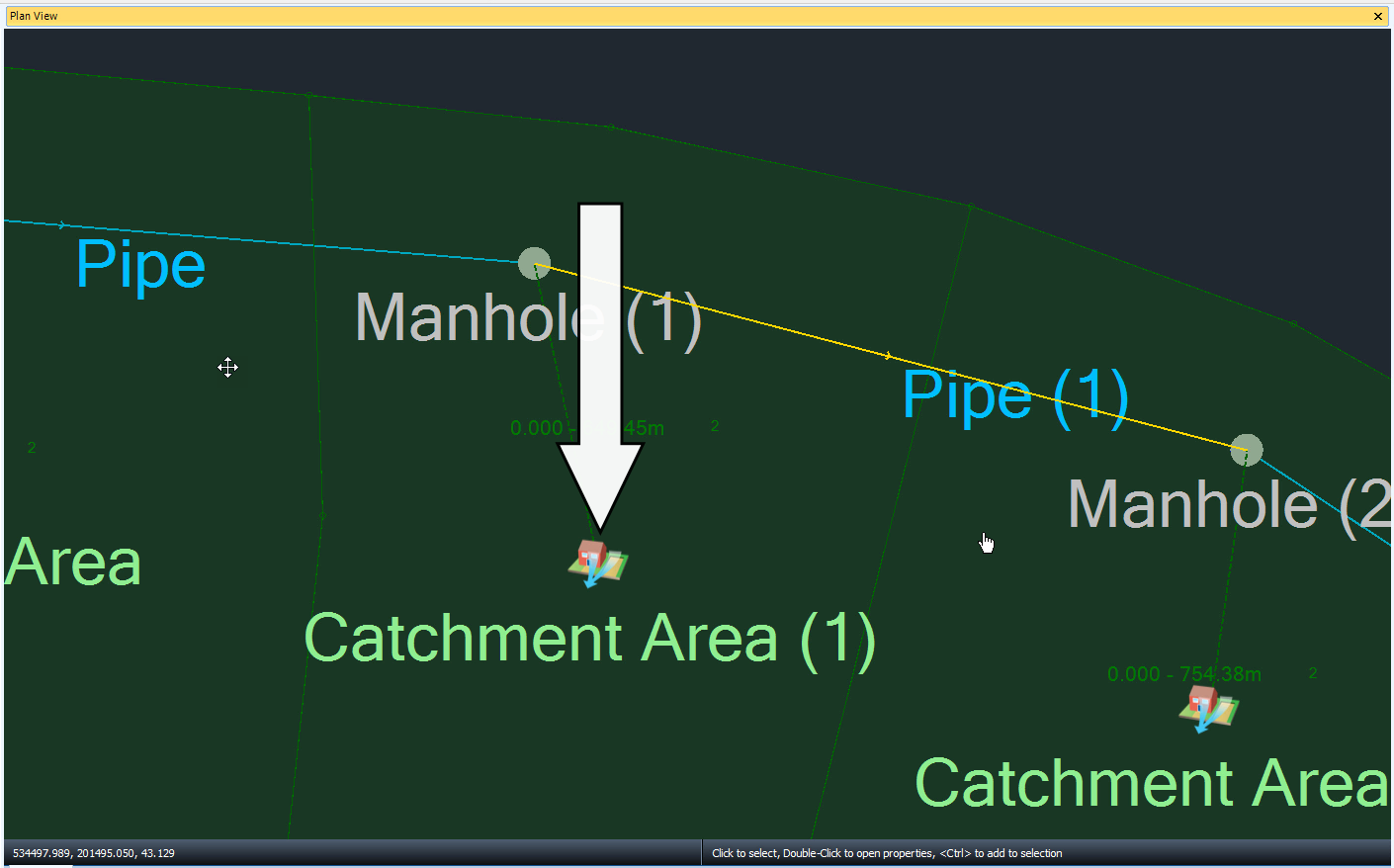
  3. The dialog box for the catchment area opens, with the Runoff tab active where you can access the data you need.
    The Catchment Area (1) dialog box.
Was this information helpful?