Merging Pressure Zones
Use the Pressure Zone Manager (PZM) to merge pressure zones.
Tutorial resources
These downloadable resources will be used to complete this tutorial:
Step-by-step:
After running a Pressure Zone Manager trace and analysis, you can merge pressure zones in your model.
- Open the appropriate .aprx file in ArcGIS Pro.
- From the ribbon, InfoWater Pro tab, Project panel, click Initialize.
In a previous PZM run, it was discovered that PZM6 should be merged with PZM3. To merge these two zones into a single pressure zone:
- On the ribbon, InfoWater Pro tab, Project panel, click Apps.
- Double-click PZM.
- In the Pressure Zone Manager, click Options.
- In the PZM Options dialog box, under Zone ID, set the Next ID Counter to 1.
- Click OK.
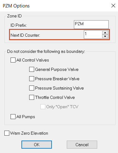
IMPORTANT: Resetting the Next ID Counter is necessary because the PZM tool has been run prior. However, if you just started, you would start with PZM7 rather than PZM1. So, make sure you reset this any time you re-run the PZM tool.
- Click New to start the Pressure Zone Wizard.
- On the first page, next to Store the element's Zone ID in this field, enter “ZoneID”.
- For Output Time, enter 00:00 hrs.
- Click Next.
- For Step 1, in the Definition of Trace Area group, select No User Defined Boundary Pipes.
- Click Next.
- On the Step 2 page, users can define intra-zone elements for the PZM to ignore them as zone delineators, but still treat them like junctions in the simulation. Click Add Row.
- In the new row, expand the Type drop-down and select Pump.

- Click Select Element.
- In the model, zoom in and select Pump P-100, or type “P-100” into the pump ID field.
Note: Pump P-100 is the north pump connected to WTP100 that was included in PZM6 in the original analysis.

- Click Add Row.
- Repeat steps 15 – 17 to add pump P-120 to a new row.
Pumps P-100 and P-120 will now be included in the closest pressure zone.
- Click Next.
- For Step 3, no boundary pipe elements are user-defined, so click Next.
- On the Step 4 page is the customized zone information for the six start nodes that was created during the earlier run. Click Clear All to remove this information.
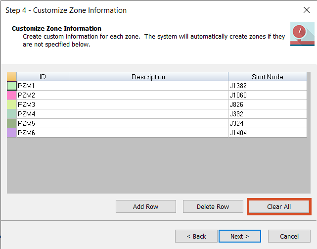
- Click Next.
- On the Trace and Analyze page, click Run.
The PZM performs a trace analysis to identify pressure zones in the model with the updated information.
Five pressure zones are created, PZM1 through PZM5. PZM6 no longer exists and is now part of PZM3.
- Click Finish to close the wizard and return to the Pressure Zone Manager.

- In the Pressure Zone Manager, click the cell above the zone list to select all the zones.
- Click Show Zone.
- Move the Pressure Zone Manager window to the side and view the map with all 5 pressure zones color-coded.

- Click Close to exit the Pressure Zone Manager.