• InfoDrainage

Adding drainage system objects to the model

Build an InfoDrainage model using Inflows, Junctions, Stormwater Controls, and Connections.


Tutorial resources

These downloadable resources will be used to complete this tutorial:


00:04

it is very easy to add predefined storm

00:06

drainage system objects into your surface model.

00:08

Using the tools in the toolbox

00:13

best practices to add the individual junction objects such as

00:16

manholes and then connect them with pipe or channel objects.

00:21

Deselect the surface to turn it off.

00:24

Although it is now invisible,

00:25

it will still be used to derive the ground

00:28

level for manholes and some of the stormwater controls.

00:32

Select the model to be digitized and then zoom into it,

00:37

click the plan tab and ensure that the snap mode is highlighted as being turned on.

00:43

Then in the toolbox,

00:44

ensure that the select tool is highlighted

00:47

and then expand the junctions node,

00:50

click manhole to activate the manhole object for placement.

00:55

Now click and drag a manhole from the toolbox into the drawing.

00:58

Hover the cursor over a point and when you see the manhole snapped to the point,

01:03

release the mouse button to place the manhole,

01:08

the select in manhole tools are still on so

01:11

that you can continue to place additional manholes.

01:15

Place manholes along the remaining points as shown in the design,

01:19

You can zoom in and out as necessary so that

01:22

you can ensure they snap to the correct location.

01:26

If you click accidentally and place a manhole in the wrong spot,

01:29

you can switch to the select tool then simply click and

01:32

drag that manhole back to the point where it should be

01:37

to ensure that it has indeed snapped correctly zoom

01:40

in so that you can focus on that object,

01:42

then click and drag it to place it precisely

01:47

notice in the tree view that as you placed each manhole

01:50

they were added under the junctions node in numerical order

01:54

you can rename them if you want by right clicking on the name and then typing a new name

02:00

for this exercise. However, leave them as the default.

02:05

If you have placed a manhole incorrectly and want

02:07

to remove it such as Manhole eight and this example

02:11

simply select it either in the plan view or

02:13

the tree view to highlight it and then press delete

02:18

as you are placing structures into your model

02:21

when you are finished placing all of them.

02:23

Best practice is to click the select tool from

02:25

the toolbox to stop the object creation mode.

02:29

This will keep you from accidentally adding too

02:31

many structure objects where you did not intend.

Video transcript

00:04

it is very easy to add predefined storm

00:06

drainage system objects into your surface model.

00:08

Using the tools in the toolbox

00:13

best practices to add the individual junction objects such as

00:16

manholes and then connect them with pipe or channel objects.

00:21

Deselect the surface to turn it off.

00:24

Although it is now invisible,

00:25

it will still be used to derive the ground

00:28

level for manholes and some of the stormwater controls.

00:32

Select the model to be digitized and then zoom into it,

00:37

click the plan tab and ensure that the snap mode is highlighted as being turned on.

00:43

Then in the toolbox,

00:44

ensure that the select tool is highlighted

00:47

and then expand the junctions node,

00:50

click manhole to activate the manhole object for placement.

00:55

Now click and drag a manhole from the toolbox into the drawing.

00:58

Hover the cursor over a point and when you see the manhole snapped to the point,

01:03

release the mouse button to place the manhole,

01:08

the select in manhole tools are still on so

01:11

that you can continue to place additional manholes.

01:15

Place manholes along the remaining points as shown in the design,

01:19

You can zoom in and out as necessary so that

01:22

you can ensure they snap to the correct location.

01:26

If you click accidentally and place a manhole in the wrong spot,

01:29

you can switch to the select tool then simply click and

01:32

drag that manhole back to the point where it should be

01:37

to ensure that it has indeed snapped correctly zoom

01:40

in so that you can focus on that object,

01:42

then click and drag it to place it precisely

01:47

notice in the tree view that as you placed each manhole

01:50

they were added under the junctions node in numerical order

01:54

you can rename them if you want by right clicking on the name and then typing a new name

02:00

for this exercise. However, leave them as the default.

02:05

If you have placed a manhole incorrectly and want

02:07

to remove it such as Manhole eight and this example

02:11

simply select it either in the plan view or

02:13

the tree view to highlight it and then press delete

02:18

as you are placing structures into your model

02:21

when you are finished placing all of them.

02:23

Best practice is to click the select tool from

02:25

the toolbox to stop the object creation mode.

02:29

This will keep you from accidentally adding too

02:31

many structure objects where you did not intend.

Step-by-step:

It is very easy to add predefined storm drainage system objects into your surface model using the tools in the Toolbox. Best practice is to add the individual junction objects, such as manholes, and then connect them with pipe or channel objects.

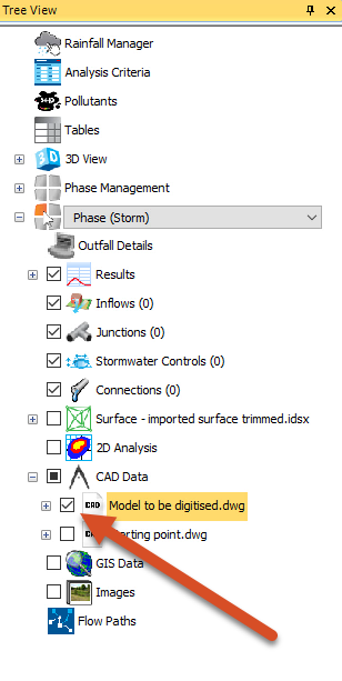
  1. From the Tree View, toggle the surface OFF.
  2. Select the file Model to be digitized.dwg.
  3. In the Plan View, zoom into it.
    Tree View with the surface visibility toggled OFF and the Model to be digitized.dwg selected.
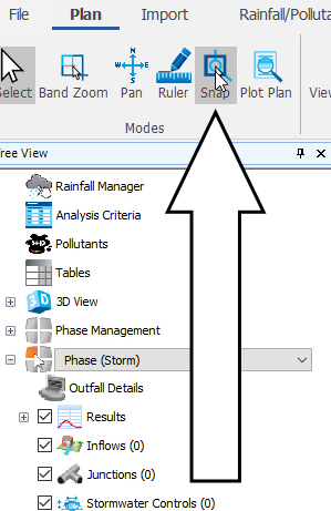
  4. On the ribbon, Plan tab, Modes panel, select Snap to enable Snap mode.
    The Plan tab with the Snap command called out.
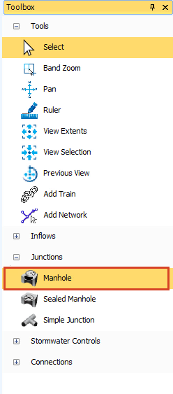
  5. In the Toolbox, expand the Junctions node and click Manhole to activate the manhole object for placement.
    The Toolbox with Junctions expanded, and Manhole selected
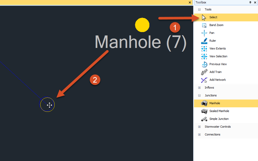
  6. Click and drag a Manhole from the Toolbox into the drawing.
  7. Hover the cursor over a point.
  8. When the manhole snaps to the point, release the mouse button to place the manhole.
    The Plan view and the Toolbox with manholes being placed in the plan and called out.
  9. Place manholes along the remaining points as shown in the design.
  10. To move a manhole, switch to the Select tool, then click and drag the manhole back to the point where it should be.
    The Plan View and Toolbox with the Select tool called out and a manhole selected.

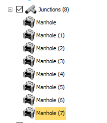
In the Tree View, the manholes were added under the Junctions node in numerical order. You can rename them by right-clicking on the name and then choosing Rename.

The Tree View showing the Junctions node expanded and the manholes listed underneath.

  1. To delete a Manhole, select it in the Plan View or the Tree View to highlight it, and then, on your keyboard, press DELETE.
Was this information helpful?