Connecting inlets and outlets
Connect inlets and outlets to a pond in a drainage system model.
Tutorial resources
These downloadable resources will be used to complete this tutorial:
Step-by-step:
Once a pond design has been incorporated into a drainage system model, it must be properly connected to the model. This includes designing an inlet that connects it to upstream pipes and an outlet that connects it to the discharge control point downstream.
- In the Tree View, right-click CAD Data and choose Import Data.
- In the Load CAD Wizard, click Select.
- In the Open dialog box, browse to the CAD file that contains the pond, such as Pond Pipe.dxf and open it.
- In the Load CAD Wizard, click Finish to import the CAD data into the model.
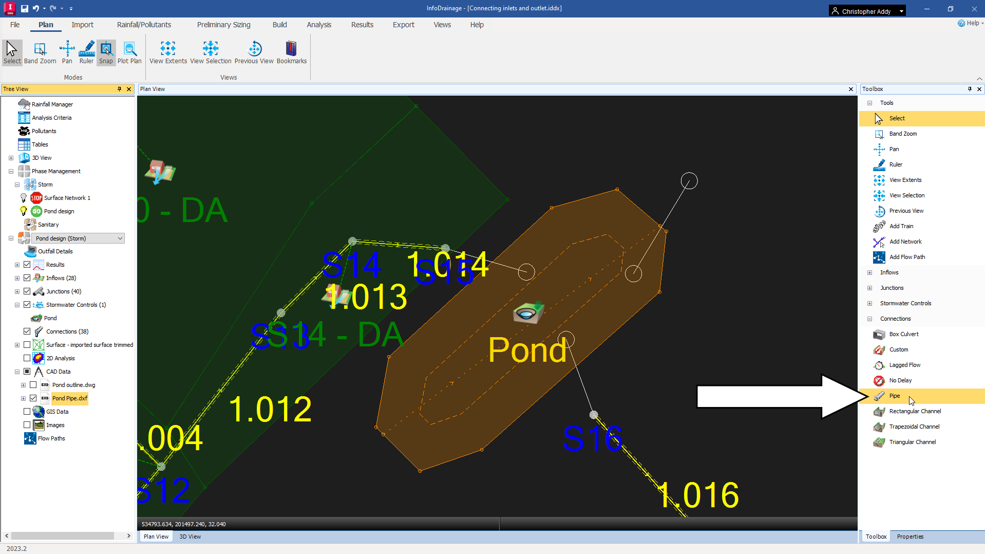
- On the ribbon, Plan tab, Modes panel, enable the Snap tool.
First, create the inlet connection.
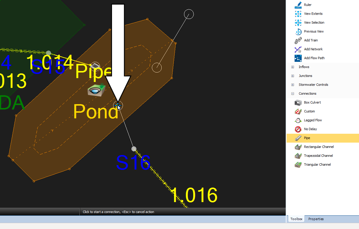
- In the Toolbox, expand the Connections node and select Pipe.
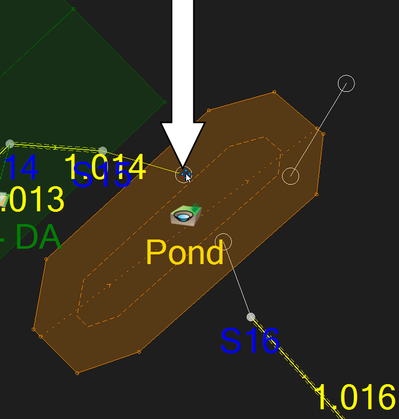
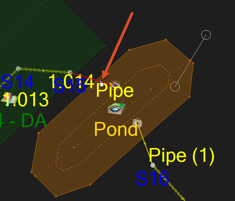
- Click and drag the pipe connection to anchor its start point to manhole S15.
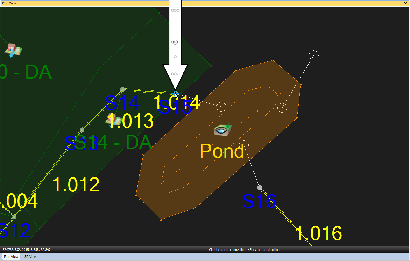
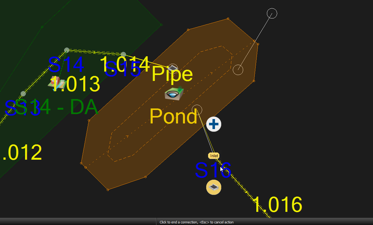
- With the connection attached to the cursor, click again following the background image to place the connection end point.
- In the Toolbox, click the Select tool to avoid creating additional connections.
- To check the connected inlet’s properties, double-click the Pond icon.
- In the Pond dialog box, select Inlets.
- Review the Inlet Type drop-down, which is set to Point Inflow by default for the single inlet just created.
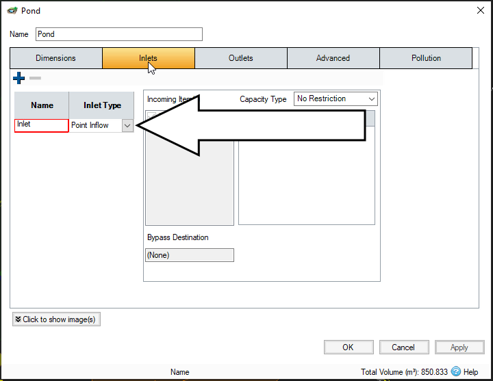
- Click OK.
Once the inlet of the pond is set, connect an outlet.
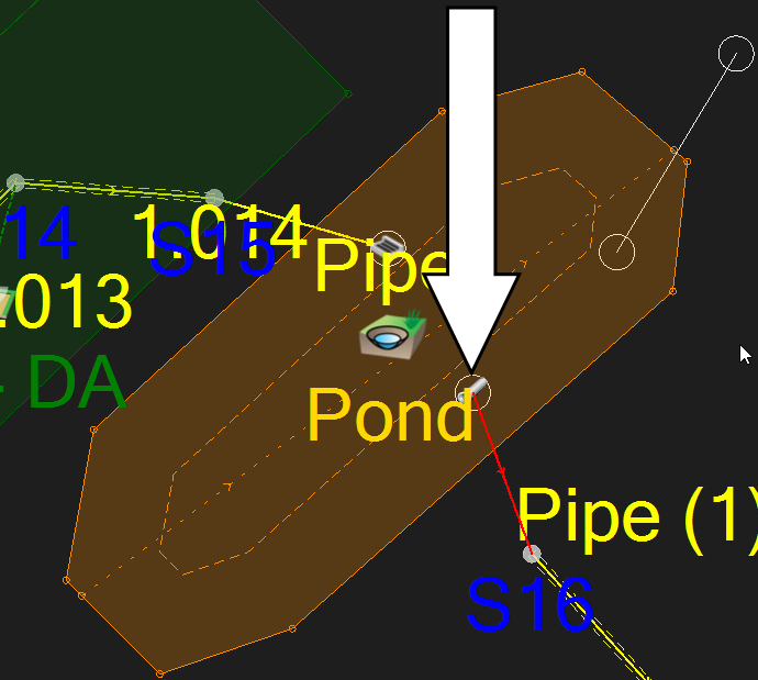
- From the Toolbox, click and drag the pipe connection to the Pond, making sure to drop the start point so that it snaps to the background image of the pipe leaving the pond.
- Drag the endpoint to the receiving manhole, (S16), situate the cursor so the manhole icon shows “Inlet,” then click to place the pipe.
- In the Toolbox, click Select.
- To check the connected outlet’s properties, double-click the outlet icon to open its properties.
- In the Pond dialog, Outlets tab, expand the Outlet Type drop-down and select Orifice.
To calculate the diameter of the orifice, so that it limits the discharge from the pond to 16.1 l/s:
- Click the Diameter Calculator icon.
- In the Diameter Calculator dialog box, set the Design Depth to 1.675 (the maximum depth in the pond up to the freeboard level).
- Set the Design Flow to 16.1 L/s (calculated previously).
- Set the Coefficient of Discharge to 0.600, if it is not already.
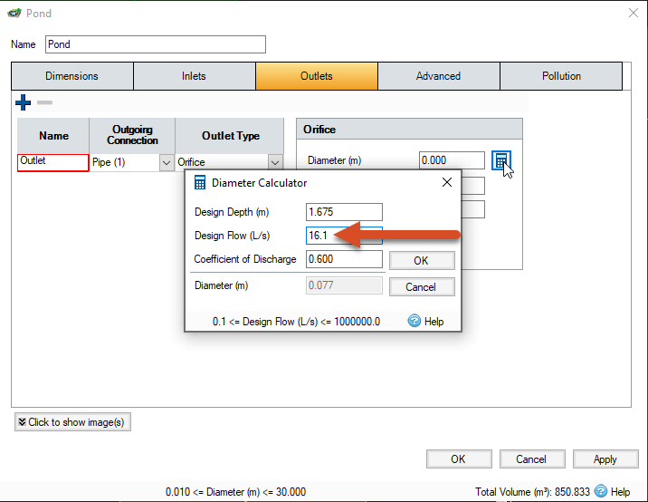
- The Diameter field reports a calculated value of 0.077 meters. Click OK to close the Diameter Calculator.
- Click OK to close the Pond dialog.
- In the Toolbox, click the Select tool.
- In the model, double-click the pipe entering the pond.
- In the Connections dialog box, set the Diameter/Base Width for both Pipe and Pipe(1) to 600 mm.
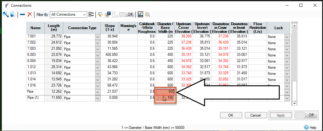
- Click OK.
To make sure the pond is properly connected to the rest of the drainage system, check the flow path.
- In the Tree View, right-click the Flow Paths node and select Add.
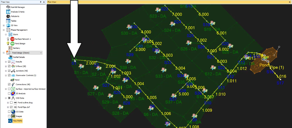
- In the model, zoom out and pan the model view to access the first manhole in the desired flow path.
- Select manhole S1.
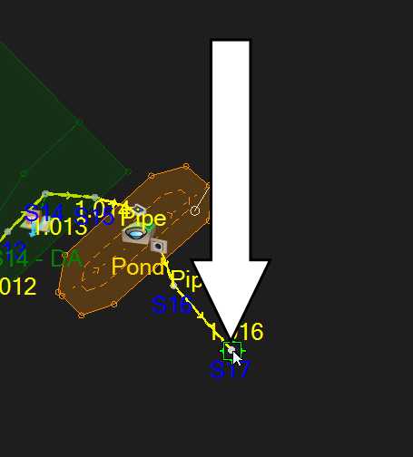
- Select manhole S17.
- In the Tree View, expand Flow Paths.
- Right-click Flow Path and select Show Profile.
Note: the flow path is highlighted in the model and its path runs through the inlet and outlet created in the pond.

- In the Profile – Flow Path dialog box, review the profile.
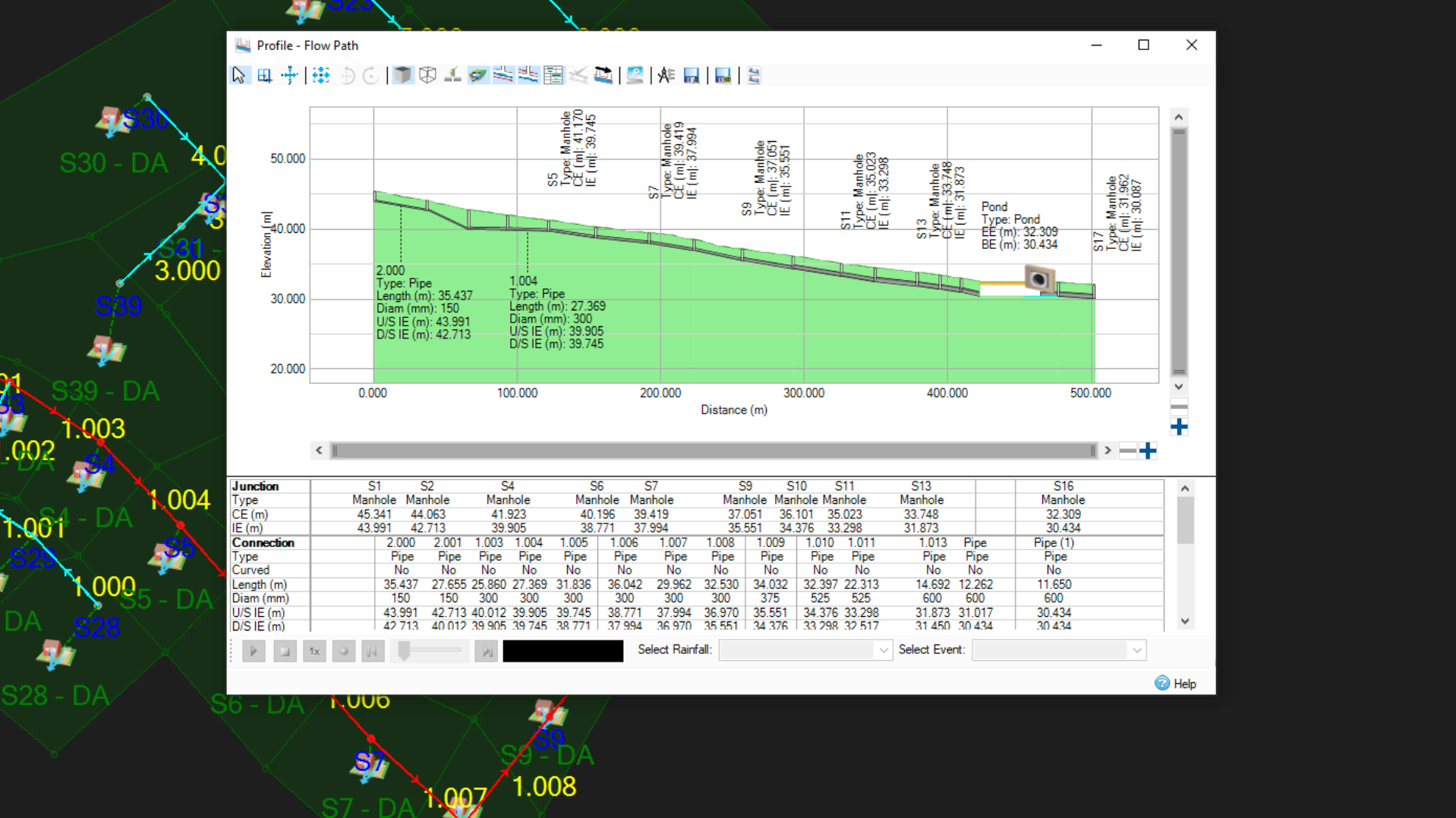
- When finished, close the dialog.