Setting up the Drawing window
Configure the drawing window, using named views, and viewports.
Divide the drawing area into separate viewports
- Open Intro-2.dwg, which is located in the tutorials drawings folder.
This drawing contains an existing ground surface, several alignments, and several profile views that contain existing ground and layout profiles.
- Click View tab
 Model Viewports panel Viewport Configuration ListTwo: Vertical.
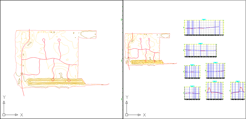
Two viewports are displayed. Each viewport is a separate window in which you can pan and zoom to different views of the drawing. You can create custom viewport configurations and save them for later use.
- Click in each of the viewports.
Notice that as you click in a viewport, the border darkens to indicate which viewport is currently active. Click the viewport on the left side to make it active.
- On the command line, enter ZE.
The surface and profile views are displayed in the left viewport.
Apply a saved drawing view
- Click the viewport on the left side to make it active.
- Click View tab Named Views panel Surface Extents.
The extents of the EG surface appears in the left viewport.
Three views have been created in this drawing. Each named view consists of a specific magnification, position, orientation, and layer status. Named views are saved with a drawing and can be used any time. When your drawing is displaying a specific view to which you want to return, you can save it as a named view by clicking View tab ![]() Views panel
Views panel ![]() View Manager.
View Manager.