• AutoCAD LT for Mac
  • AutoCAD LT

Draw and modify geometry in AutoCAD LT

Create lines, circles, hatches, rectangles, and more.


Learn how to create and organize 2D objects using layers, basic drawing tools, ortho, and object snap.

00:04

let's take a look at some basic commands you might use as you create a drawing.

00:08

We'll begin by looking at layers

00:11

layers allow you to organize the objects in your drawing.

00:14

You can group similar objects so you can easily

00:17

turn them off or on for displaying or printing

00:20

and you can lock layers

00:22

to prevent unwanted changes.

00:26

I'll open the layer, Properties Manager.

00:29

This is where you create and manage your layers.

00:32

I'm going to add a new layer called objects to this drawing.

00:36

I double click to make it the current layer so

00:38

that the objects I draw added to it automatically.

00:42

I'll start drawing using the line command.

00:45

Typically when you start a command

00:47

you'll be prompted to input a value or specifying option.

00:51

The input expected is displayed as a prompt in the command line

00:54

and as a tool tip near the cursor.

00:56

If dynamic input is turned on I'll turn dynamic input off for now

01:04

to indicate the first point of my line

01:06

I click in the drawing area.

01:08

Now I'm prompted for the next point.

01:10

I drag the cursor and click again

01:13

the line command continues to prompt for additional points until I end the command

01:18

to end.

01:18

I can press escape,

01:19

enter or the space bar where I can right click and choose enter from the menu

01:25

to control drawing precision. I can choose from a variety of drafting aids

01:30

for example,

01:31

the Ortho mode button constrains me to vertical and horizontal lines as I draw,

01:37

alter an Ortho off Again,

01:39

object snaps also known as Oh snaps allow me to

01:42

easily place new objects in relation to existing objects.

01:46

I'll use the endpoint object snap to connect a new

01:49

line to the endpoint of the existing line I've drawn.

01:53

The auto snap marker makes it easy to know which object snap is being used.

Video transcript

00:04

let's take a look at some basic commands you might use as you create a drawing.

00:08

We'll begin by looking at layers

00:11

layers allow you to organize the objects in your drawing.

00:14

You can group similar objects so you can easily

00:17

turn them off or on for displaying or printing

00:20

and you can lock layers

00:22

to prevent unwanted changes.

00:26

I'll open the layer, Properties Manager.

00:29

This is where you create and manage your layers.

00:32

I'm going to add a new layer called objects to this drawing.

00:36

I double click to make it the current layer so

00:38

that the objects I draw added to it automatically.

00:42

I'll start drawing using the line command.

00:45

Typically when you start a command

00:47

you'll be prompted to input a value or specifying option.

00:51

The input expected is displayed as a prompt in the command line

00:54

and as a tool tip near the cursor.

00:56

If dynamic input is turned on I'll turn dynamic input off for now

01:04

to indicate the first point of my line

01:06

I click in the drawing area.

01:08

Now I'm prompted for the next point.

01:10

I drag the cursor and click again

01:13

the line command continues to prompt for additional points until I end the command

01:18

to end.

01:18

I can press escape,

01:19

enter or the space bar where I can right click and choose enter from the menu

01:25

to control drawing precision. I can choose from a variety of drafting aids

01:30

for example,

01:31

the Ortho mode button constrains me to vertical and horizontal lines as I draw,

01:37

alter an Ortho off Again,

01:39

object snaps also known as Oh snaps allow me to

01:42

easily place new objects in relation to existing objects.

01:46

I'll use the endpoint object snap to connect a new

01:49

line to the endpoint of the existing line I've drawn.

01:53

The auto snap marker makes it easy to know which object snap is being used.

Create basic geometry such as lines, circles, and hatched areas. You can create a lot of different geometric object types in AutoCAD LT, but you only need to know a few of them for most 2D drawings.


Drawing lines

Use the LINE command to create a series of line segments.

00:03

Lines consist of straight line segments.

00:06

Before you draw your first line, look at the command line and notice that it currently prompts you to type a command.

00:14

Any time you see this, it means that there is no active command.

00:18

Instead, the program is waiting for you to start a command.

00:22

To create a line, move the cursor over the Line tool, in the Draw panel on the Home Ribbon, but do not click yet.

00:31

Notice that when you move the cursor over a button, a tooltip appears that tells you basic information about that tool.

00:39

The tooltip then expands to display more information.

00:43

In this case, the extended tooltip shows that with the line command, you can create a series of contiguous line segments,

00:50

and that each segment is a line object that can be edited separately.

00:55

Now, click the Line tool.

00:58

When you start the Line command on the command line, you can see that the Line command is now active.

01:05

You can see the name of the command.

01:07

You can also see that the program is prompting you to Specify first point:.

01:12

Notice that you can also see this same prompt adjacent to the cursor.

01:17

This is called dynamic input.

01:20

It is a very handy feature, because you can see what the program is expecting you to do next

01:25

without having to take your eyes off the cursor and look back down at the command line.

01:30

Click anywhere in the drawing to specify the starting point of the line.

01:35

As soon as you specify the starting point, the prompt changes.

01:40

Now the program is prompting you to Specify next point, and in the command line you are prompted to Specify next point or [Undo]:.

01:51

Notice that you can see a line extending from the point you just picked to the cursor.

01:56

That line stretches as you move the mouse.

02:01

Click to pick another point.

02:03

As soon as you do, the program creates a line between the two points you specified, and the prompt repeats.

02:10

It again tells you to Specify next point:.

02:15

When you Click to pick another point, the program draws another line segment and the prompt repeats again.

02:22

But notice that the prompt and the command line is changed.

02:26

It now prompts you to Specify next point or [Close Undo].

02:31

And the words Close and Undo are inside square brackets and have a gray background.

02:38

Whenever you see anything inside square brackets on the command line, those are options.

02:44

That means that in addition to specifying the next point,

02:48

you can choose one of those options.

02:50

And there are several different ways that you can choose one of those options.

02:54

You can type the capital letter corresponding to the option you want to select, or you can simply click on the option in the command line.

03:03

For example, click the Undo option and the program eliminates the line segment you just created.

03:10

You could have also typed the letter U and pressed Enter, but clicking the option is much faster and easier.

03:18

If you click Undo again, the line segment before that is removed.

03:23

You can actually keep undoing the previous line segment until you have removed the very first line segment that you created,

03:30

in which case the command goes back to its very first prompt, Specify first point:.

03:35

Click to specify a point again to create one line segment.

03:40

With just one line segment created, the only option available is Undo.

03:45

Now pick another point to create a second line segment.

03:50

Once you have created two or more line segments, the close option becomes available.

03:56

When you select this option, the program draws a line segment from the endpoint of the most recent line,

04:02

back to the very first point you specified when you started the Line command.

04:07

This also ends the command.

04:10

You can see that the command has ended, because in the command line, the program once again tells you to type a command.

Video transcript

00:03

Lines consist of straight line segments.

00:06

Before you draw your first line, look at the command line and notice that it currently prompts you to type a command.

00:14

Any time you see this, it means that there is no active command.

00:18

Instead, the program is waiting for you to start a command.

00:22

To create a line, move the cursor over the Line tool, in the Draw panel on the Home Ribbon, but do not click yet.

00:31

Notice that when you move the cursor over a button, a tooltip appears that tells you basic information about that tool.

00:39

The tooltip then expands to display more information.

00:43

In this case, the extended tooltip shows that with the line command, you can create a series of contiguous line segments,

00:50

and that each segment is a line object that can be edited separately.

00:55

Now, click the Line tool.

00:58

When you start the Line command on the command line, you can see that the Line command is now active.

01:05

You can see the name of the command.

01:07

You can also see that the program is prompting you to Specify first point:.

01:12

Notice that you can also see this same prompt adjacent to the cursor.

01:17

This is called dynamic input.

01:20

It is a very handy feature, because you can see what the program is expecting you to do next

01:25

without having to take your eyes off the cursor and look back down at the command line.

01:30

Click anywhere in the drawing to specify the starting point of the line.

01:35

As soon as you specify the starting point, the prompt changes.

01:40

Now the program is prompting you to Specify next point, and in the command line you are prompted to Specify next point or [Undo]:.

01:51

Notice that you can see a line extending from the point you just picked to the cursor.

01:56

That line stretches as you move the mouse.

02:01

Click to pick another point.

02:03

As soon as you do, the program creates a line between the two points you specified, and the prompt repeats.

02:10

It again tells you to Specify next point:.

02:15

When you Click to pick another point, the program draws another line segment and the prompt repeats again.

02:22

But notice that the prompt and the command line is changed.

02:26

It now prompts you to Specify next point or [Close Undo].

02:31

And the words Close and Undo are inside square brackets and have a gray background.

02:38

Whenever you see anything inside square brackets on the command line, those are options.

02:44

That means that in addition to specifying the next point,

02:48

you can choose one of those options.

02:50

And there are several different ways that you can choose one of those options.

02:54

You can type the capital letter corresponding to the option you want to select, or you can simply click on the option in the command line.

03:03

For example, click the Undo option and the program eliminates the line segment you just created.

03:10

You could have also typed the letter U and pressed Enter, but clicking the option is much faster and easier.

03:18

If you click Undo again, the line segment before that is removed.

03:23

You can actually keep undoing the previous line segment until you have removed the very first line segment that you created,

03:30

in which case the command goes back to its very first prompt, Specify first point:.

03:35

Click to specify a point again to create one line segment.

03:40

With just one line segment created, the only option available is Undo.

03:45

Now pick another point to create a second line segment.

03:50

Once you have created two or more line segments, the close option becomes available.

03:56

When you select this option, the program draws a line segment from the endpoint of the most recent line,

04:02

back to the very first point you specified when you started the Line command.

04:07

This also ends the command.

04:10

You can see that the command has ended, because in the command line, the program once again tells you to type a command.

Understanding object snap concepts

Object snap causes the cursor to snap to precise locations on objects.

00:03

Object Snap causes the cursor to snap to precise locations on objects, and is essential to creating accurate drawings.

00:10

You can use object snaps to create a line to the center of a circle or to the midpoint of another line.

00:17

For example, when it is zoomed out so that you can see this entire floor plan, this drawing looks pretty good,

00:24

but when you zoom in to get a closer look at the lower left corner of the drawing, you can see that the lines were not created accurately.

00:31

Some lines are too short, and some lines overlap.

00:35

Whoever created this drawing did not use object snaps,

00:39

and if you do not use Object Snap, your drawing is likely to contain inaccuracies such as these.

00:45

Using Object Snap is actually quite easy.

00:48

You can specify an object snap whenever you are prompted for a point.

00:53

For example, start the Line command and then move the cursor near the left end of the line.

00:59

A marker and tooltip are displayed to let you know that the program has found the endpoint of the line.

01:05

This feature, called AutoSnap, provides visual confirmation that indicates which object snap is in effect.

01:12

For example, the marker for an endpoint object snap is a square.

01:17

There are several ways you can specify an object snap.

01:21

In this example, the object snap was activated automatically as soon as you started the command.

01:28

This is called a running object snap.

01:31

When you need to use one or more object snaps repeatedly,

01:34

you can turn on running object snap so that they are active whenever you use a command.

01:40

To toggle running object snap on and off, click the object snap button on the status bar.

01:46

You can also toggle this on and off by pressing the F3 key.

01:50

To control which object snap modes are active, when running, object snap is toggled on,

01:56

click the adjacent arrow to display a menu showing all of the available object snaps, and choose the ones you want to be active.

02:04

For example, right now only the endpoint object snap is active.

02:09

You can also specify an object snap anytime the program prompts you to specify a point.

02:15

This is called an object snap override.

02:19

As its name implies, an object snap override takes precedence over any running object snap,

02:25

and stays in effect only for the next point that you specify.

02:29

You can specify an object snap override by choosing from a shortcut menu, or by typing the name of the object snap.

02:37

For example, start the Line command again, then press Shift and right-click to display the object snap shortcut menu,

02:45

and then choose Midpoint.

02:48

Now, move the cursor over the upper line.

02:51

Even though endpoint is still active as a running object snap, the program ignores that and instead finds the midpoint of the line.

02:60

Click to select the midpoint of the line and then move the cursor over the lower line.

03:05

Since the midpoint was a onetime object snap override,

03:09

the program reverts back to the running object snap mode and finds the endpoint of the line.

Video transcript

00:03

Object Snap causes the cursor to snap to precise locations on objects, and is essential to creating accurate drawings.

00:10

You can use object snaps to create a line to the center of a circle or to the midpoint of another line.

00:17

For example, when it is zoomed out so that you can see this entire floor plan, this drawing looks pretty good,

00:24

but when you zoom in to get a closer look at the lower left corner of the drawing, you can see that the lines were not created accurately.

00:31

Some lines are too short, and some lines overlap.

00:35

Whoever created this drawing did not use object snaps,

00:39

and if you do not use Object Snap, your drawing is likely to contain inaccuracies such as these.

00:45

Using Object Snap is actually quite easy.

00:48

You can specify an object snap whenever you are prompted for a point.

00:53

For example, start the Line command and then move the cursor near the left end of the line.

00:59

A marker and tooltip are displayed to let you know that the program has found the endpoint of the line.

01:05

This feature, called AutoSnap, provides visual confirmation that indicates which object snap is in effect.

01:12

For example, the marker for an endpoint object snap is a square.

01:17

There are several ways you can specify an object snap.

01:21

In this example, the object snap was activated automatically as soon as you started the command.

01:28

This is called a running object snap.

01:31

When you need to use one or more object snaps repeatedly,

01:34

you can turn on running object snap so that they are active whenever you use a command.

01:40

To toggle running object snap on and off, click the object snap button on the status bar.

01:46

You can also toggle this on and off by pressing the F3 key.

01:50

To control which object snap modes are active, when running, object snap is toggled on,

01:56

click the adjacent arrow to display a menu showing all of the available object snaps, and choose the ones you want to be active.

02:04

For example, right now only the endpoint object snap is active.

02:09

You can also specify an object snap anytime the program prompts you to specify a point.

02:15

This is called an object snap override.

02:19

As its name implies, an object snap override takes precedence over any running object snap,

02:25

and stays in effect only for the next point that you specify.

02:29

You can specify an object snap override by choosing from a shortcut menu, or by typing the name of the object snap.

02:37

For example, start the Line command again, then press Shift and right-click to display the object snap shortcut menu,

02:45

and then choose Midpoint.

02:48

Now, move the cursor over the upper line.

02:51

Even though endpoint is still active as a running object snap, the program ignores that and instead finds the midpoint of the line.

02:60

Click to select the midpoint of the line and then move the cursor over the lower line.

03:05

Since the midpoint was a onetime object snap override,

03:09

the program reverts back to the running object snap mode and finds the endpoint of the line.

Drawing circles using radius and diameter

There are several ways to define a circle in AutoCAD LT.

00:03

A circle is one of the most basic objects you can create.

00:07

To draw a circle, on the Home ribbon, in the Draw panel, click the Circle tool.

00:13

Notice that if you expand the Circle Split button, you can see that there are a number of different ways in which you can create circles.

00:21

If you pause your cursor over one of these methods, you see a tool tip describing that option.

00:28

The tool tip also shows you that the name of the command in each case is “CIRCLE”.

00:34

Each method simply preselects some of the possible Circle command options.

00:40

Let's look at the Center, Radius method.

00:44

When you click the Circle by center radius option, the program prompts you to specify the center point for the circle.

00:53

In the command window, you can see that the Circle command has several options.

00:58

You can pick the point where you would like the center of the circle to be located, or you could type in the coordinate location.

01:06

By pressing the Tab key, you can toggle between the X coordinate location and the Y coordinate location.

01:14

Remember that the program uses a Cartesian coordinate system of X and Y coordinates.

01:21

Now you can position the center of the circle.

01:24

Type “5” in the X coordinate field, then press the Tab key to switch to the other field, and type “6” to specify the location in the Y direction.

01:36

When you press the Tab key again, it locks in that value.

01:41

To finalize the selection of that point, press the Enter key.

01:47

Once you specify the center of the circle, the program prompts you to specify the radius.

01:53

The radius can also be specified by picking points or typing the radius value.

01:60

Suppose you want the radius to be exactly 0.75.

02:05

Type that value and then press enter to create that circle.

02:10

Repeat the command by pressing the Spacebar.

02:13

This time, pick the location for the center of the circle.

02:18

Then you can simply move the cursor and click to specify a new radius.

02:24

But before you do that, look at the command line.

02:28

Notice that the program is prompting you to specify the radius of the circle.

02:33

You also have the option of specifying the diameter of the circle, but there is also a default value which is shown inside angle brackets.

02:43

The program remembers the radius of the previous circle and displays that value as the default.

02:50

So, if you want to create another circle of the exact same size,

02:55

you can simply press Enter to accept that default value.

02:59

Press the Spacebar to repeat the command again, pick the center point, and then enter a new radius of 1.25.

03:10

Then, if you start the command again after you specify the center point,

03:16

now the command shows you the radius of the most recent circle, in this case 1.25, as the new default value.

03:25

Start the circle command again, but this time choose the Center, Diameter method.

03:31

Again, the program prompts you to specify the center of the circle,

03:36

but notice that this time, after you select the center point,

03:40

the command prompts you to specify the diameter of the circle, rather than the radius.

03:46

In the drawing window, you can see the diameter and the default value is now 2.5.

03:52

That is the diameter value of the last circle you created.

03:56

So, the program still remembers the size of the previous circle and offers it as the default value for the new circle.

04:04

However, since you specified that you wanted to create the circle based on its diameter instead of its radius,

04:10

it has now converted the default into a diameter value.

04:14

If you look carefully in the command line, you can see exactly what happened.

04:19

The previous circle had a radius of 1.25.

04:23

Selecting the Center, Diameter method in the ribbon automatically chose the Diameter option.

04:29

You can see the letter “D” right there on the command line.

04:33

So, the prompt changed to specify diameter, and the new default value appears as the diameter value.

04:41

If you press the Enter key, you create a circle the same size as the previous circle.

04:47

Start the command again by pressing the Spacebar, and then specify the center of the circle.

04:54

But notice that the command has gone back to prompting you to specify the radius of the circle, which is the default method for creating circles.

05:03

If you want to specify the diameter instead, you can click to select the Diameter option.

05:09

Type the letter “D”, or right-click and choose Diameter from the shortcut menu.

05:16

Or, with Dynamic Input enabled, you can press the Down arrow key and choose Diameter.

05:23

Then you can specify the diameter of the circle.

Video transcript

00:03

A circle is one of the most basic objects you can create.

00:07

To draw a circle, on the Home ribbon, in the Draw panel, click the Circle tool.

00:13

Notice that if you expand the Circle Split button, you can see that there are a number of different ways in which you can create circles.

00:21

If you pause your cursor over one of these methods, you see a tool tip describing that option.

00:28

The tool tip also shows you that the name of the command in each case is “CIRCLE”.

00:34

Each method simply preselects some of the possible Circle command options.

00:40

Let's look at the Center, Radius method.

00:44

When you click the Circle by center radius option, the program prompts you to specify the center point for the circle.

00:53

In the command window, you can see that the Circle command has several options.

00:58

You can pick the point where you would like the center of the circle to be located, or you could type in the coordinate location.

01:06

By pressing the Tab key, you can toggle between the X coordinate location and the Y coordinate location.

01:14

Remember that the program uses a Cartesian coordinate system of X and Y coordinates.

01:21

Now you can position the center of the circle.

01:24

Type “5” in the X coordinate field, then press the Tab key to switch to the other field, and type “6” to specify the location in the Y direction.

01:36

When you press the Tab key again, it locks in that value.

01:41

To finalize the selection of that point, press the Enter key.

01:47

Once you specify the center of the circle, the program prompts you to specify the radius.

01:53

The radius can also be specified by picking points or typing the radius value.

01:60

Suppose you want the radius to be exactly 0.75.

02:05

Type that value and then press enter to create that circle.

02:10

Repeat the command by pressing the Spacebar.

02:13

This time, pick the location for the center of the circle.

02:18

Then you can simply move the cursor and click to specify a new radius.

02:24

But before you do that, look at the command line.

02:28

Notice that the program is prompting you to specify the radius of the circle.

02:33

You also have the option of specifying the diameter of the circle, but there is also a default value which is shown inside angle brackets.

02:43

The program remembers the radius of the previous circle and displays that value as the default.

02:50

So, if you want to create another circle of the exact same size,

02:55

you can simply press Enter to accept that default value.

02:59

Press the Spacebar to repeat the command again, pick the center point, and then enter a new radius of 1.25.

03:10

Then, if you start the command again after you specify the center point,

03:16

now the command shows you the radius of the most recent circle, in this case 1.25, as the new default value.

03:25

Start the circle command again, but this time choose the Center, Diameter method.

03:31

Again, the program prompts you to specify the center of the circle,

03:36

but notice that this time, after you select the center point,

03:40

the command prompts you to specify the diameter of the circle, rather than the radius.

03:46

In the drawing window, you can see the diameter and the default value is now 2.5.

03:52

That is the diameter value of the last circle you created.

03:56

So, the program still remembers the size of the previous circle and offers it as the default value for the new circle.

04:04

However, since you specified that you wanted to create the circle based on its diameter instead of its radius,

04:10

it has now converted the default into a diameter value.

04:14

If you look carefully in the command line, you can see exactly what happened.

04:19

The previous circle had a radius of 1.25.

04:23

Selecting the Center, Diameter method in the ribbon automatically chose the Diameter option.

04:29

You can see the letter “D” right there on the command line.

04:33

So, the prompt changed to specify diameter, and the new default value appears as the diameter value.

04:41

If you press the Enter key, you create a circle the same size as the previous circle.

04:47

Start the command again by pressing the Spacebar, and then specify the center of the circle.

04:54

But notice that the command has gone back to prompting you to specify the radius of the circle, which is the default method for creating circles.

05:03

If you want to specify the diameter instead, you can click to select the Diameter option.

05:09

Type the letter “D”, or right-click and choose Diameter from the shortcut menu.

05:16

Or, with Dynamic Input enabled, you can press the Down arrow key and choose Diameter.

05:23

Then you can specify the diameter of the circle.

Drawing rectangles

The RECTANG command creates a closed rectangular polyline.

Ortho mode restricts cursor movement to horizontal and vertical directions. Learn how to achieve the precision required for your models.

00:03

Ortho mode restricts cursor movement to horizontal and vertical directions for convenience and precision

00:09

when creating and modifying objects.

00:13

Ortho mode is initially toggled off by default.

00:16

You can toggle Ortho mode on and off using the Restrict Cursor Orthogonally button on the status bar.

00:24

When you move the cursor over this button, you can see that Ortho mode is currently off.

00:29

Click this button to toggle it on.

00:32

The button changes color, and the tooltip indicates that Ortho mode is now on.

00:37

On the Home ribbon, in the Draw panel, click the Line tool and then click to specify the first point of the line.

00:45

When Ortho mode is on, the program will only allow you to draw lines that are perfectly horizontal or vertical.

00:52

With Dynamic Input toggled on, the program displays the length of the line.

00:57

It also displays a tool tip that shows you that the line is constrained to the orthographic directions of 0, 90, 180, or 270 degrees.

01:09

Click the button on the status bar to toggle off Ortho mode.

01:13

Now when you draw line segments, the Dynamic Input tooltip no longer includes the word “Ortho:”,

01:20

and you can draw lines at whatever angle you choose.

01:23

Move the cursor over the button on the status bar again.

01:27

in the tooltip, note that you can also toggle Ortho mode on and off, by pressing the F8 key.

01:34

Press F8 once to toggle it back on.

01:37

The button on the status bar changes color.

01:40

The cursor is again constrained to 90 degree angles, and you can see the word Ortho: adjacent to the cursor.

01:47

When you press the F8 key again, Ortho mode is turned back off.

01:52

So, when you want to create geometry that is perfectly horizontal or vertical, you can turn on ortho mode,

01:58

and when you want to draw at any angle you can turn it back off by using the button on the status bar, or by pressing the F8 key.

Video transcript

00:03

Ortho mode restricts cursor movement to horizontal and vertical directions for convenience and precision

00:09

when creating and modifying objects.

00:13

Ortho mode is initially toggled off by default.

00:16

You can toggle Ortho mode on and off using the Restrict Cursor Orthogonally button on the status bar.

00:24

When you move the cursor over this button, you can see that Ortho mode is currently off.

00:29

Click this button to toggle it on.

00:32

The button changes color, and the tooltip indicates that Ortho mode is now on.

00:37

On the Home ribbon, in the Draw panel, click the Line tool and then click to specify the first point of the line.

00:45

When Ortho mode is on, the program will only allow you to draw lines that are perfectly horizontal or vertical.

00:52

With Dynamic Input toggled on, the program displays the length of the line.

00:57

It also displays a tool tip that shows you that the line is constrained to the orthographic directions of 0, 90, 180, or 270 degrees.

01:09

Click the button on the status bar to toggle off Ortho mode.

01:13

Now when you draw line segments, the Dynamic Input tooltip no longer includes the word “Ortho:”,

01:20

and you can draw lines at whatever angle you choose.

01:23

Move the cursor over the button on the status bar again.

01:27

in the tooltip, note that you can also toggle Ortho mode on and off, by pressing the F8 key.

01:34

Press F8 once to toggle it back on.

01:37

The button on the status bar changes color.

01:40

The cursor is again constrained to 90 degree angles, and you can see the word Ortho: adjacent to the cursor.

01:47

When you press the F8 key again, Ortho mode is turned back off.

01:52

So, when you want to create geometry that is perfectly horizontal or vertical, you can turn on ortho mode,

01:58

and when you want to draw at any angle you can turn it back off by using the button on the status bar, or by pressing the F8 key.

Check out the Handy Function Key Reference Table to learn how to:

  • Turn the grid display on and off [F7]
  • Lock cursor movement to horizontal or vertical [F8]
  • Restrict cursor movement to specified intervals with the grid snap tool [F9]

Modify 2D objects

Learn how to select and modify 2D objects using window selection, erase, zoom, and copy.

Using the MOVE command

The MOVE command enables you to move select objects to a new position.

00:03

The Move command enables you to move selected objects to a new position

00:07

at a specified distance and direction from their original location.

00:11

Like most Modify commands, the Move command works in a two-step process.

00:16

First, you select the object or objects, and then you perform the actual command action.

00:23

For example, when you start the Move command, the program first prompts you to select the objects you want to move,

00:29

and you can use any convenient object selection method.

00:33

You can click to pick the objects, use a selection window or crossing window, and so on.

00:39

Once you are done selecting the objects you want to move,

00:43

you can right-click or press Enter to indicate that you have finished selecting objects.

00:48

At that point, the program shifts to the action portion of the command,

00:52

in which it prompts you for a base point and a second point of displacement.

00:57

Zoom into the bedroom in the lower right corner.

01:00

Suppose you want to move the bed to a different location.

01:04

On the Home ribbon, in the Modify panel, click the Move tool.

01:09

The program prompts you to select objects, and you can use any object selection method.

01:15

In this case, use a selection window.

01:19

Once you see that the objects have been selected, right-click to go on to the action part of the command.

01:25

Now the program prompts you for the base point.

01:28

You can enter the X and Y coordinates of that base point, or just click to pick a point in the drawing.

01:35

Click to pick a point, which does not even have to be located on the objects you are moving.

01:40

Once you pick the base point, the program prompts you for a second point, or you can use the first point as the displacement.

01:48

As you move the cursor, the selected objects appear with a faded appearance in their original position,

01:54

and you can also see a preview of the objects being moved.

01:58

The program is asking for a relative distance and angle.

02:02

You can enter those values or simply click to pick a point.

02:06

You could simply pick the second point, but suppose that you want to move the bed exactly 24 units.

02:13

With the distance field active, type “24”, and then press the Tab key.

02:19

As soon as you do, the distance is locked in, but you can still move the cursor to change the angle.

02:25

If you know that you want to simply move the bed over to the right, you can type “0” in the angle field,

02:32

and then press the Tab key again.

02:34

Now, both the distance and angle are locked in.

02:38

You can still press the Tab key to switch between the Dynamic Input fields and change those values.

02:44

Press Enter. When you do, the bed is moved to the new location that you specified.

Video transcript

00:03

The Move command enables you to move selected objects to a new position

00:07

at a specified distance and direction from their original location.

00:11

Like most Modify commands, the Move command works in a two-step process.

00:16

First, you select the object or objects, and then you perform the actual command action.

00:23

For example, when you start the Move command, the program first prompts you to select the objects you want to move,

00:29

and you can use any convenient object selection method.

00:33

You can click to pick the objects, use a selection window or crossing window, and so on.

00:39

Once you are done selecting the objects you want to move,

00:43

you can right-click or press Enter to indicate that you have finished selecting objects.

00:48

At that point, the program shifts to the action portion of the command,

00:52

in which it prompts you for a base point and a second point of displacement.

00:57

Zoom into the bedroom in the lower right corner.

01:00

Suppose you want to move the bed to a different location.

01:04

On the Home ribbon, in the Modify panel, click the Move tool.

01:09

The program prompts you to select objects, and you can use any object selection method.

01:15

In this case, use a selection window.

01:19

Once you see that the objects have been selected, right-click to go on to the action part of the command.

01:25

Now the program prompts you for the base point.

01:28

You can enter the X and Y coordinates of that base point, or just click to pick a point in the drawing.

01:35

Click to pick a point, which does not even have to be located on the objects you are moving.

01:40

Once you pick the base point, the program prompts you for a second point, or you can use the first point as the displacement.

01:48

As you move the cursor, the selected objects appear with a faded appearance in their original position,

01:54

and you can also see a preview of the objects being moved.

01:58

The program is asking for a relative distance and angle.

02:02

You can enter those values or simply click to pick a point.

02:06

You could simply pick the second point, but suppose that you want to move the bed exactly 24 units.

02:13

With the distance field active, type “24”, and then press the Tab key.

02:19

As soon as you do, the distance is locked in, but you can still move the cursor to change the angle.

02:25

If you know that you want to simply move the bed over to the right, you can type “0” in the angle field,

02:32

and then press the Tab key again.

02:34

Now, both the distance and angle are locked in.

02:38

You can still press the Tab key to switch between the Dynamic Input fields and change those values.

02:44

Press Enter. When you do, the bed is moved to the new location that you specified.

Trimming Objects 

Delete an object or remove part of one where it crosses another object.

Layer 0 is the default layer that exists in all drawings. Instead of using this layer, experienced users recommend creating your own layers with meaningful names. Learn more about creating new layers.

00:03

When you begin working on a drawing, it will always have a layer 0.

00:07

Depending on the template used to start the drawing, it may already contain other layers as well,

00:13

but you may find that you need to add additional layers.

00:17

You can create new layers using the Layer Properties Manager palette.

00:21

On the Home ribbon, in the Layers panel, click the Layer Properties button to open the Layer Properties Manager palette.

00:30

In the Layer Properties Manager, click the New Layer button.

00:35

The program immediately adds a new layer with a default name, such as layer 1.

00:41

That new layer automatically takes on the same properties as whatever layer had previously been selected in the Layer Properties Manager.

00:49

For example, if layer 0 had been selected, the new layer would have the same color, line type, and line weight properties as layer 0.

01:00

Select the door layer and then click the New Layer button.

01:06

The new layer has the same properties as the door layer.

01:10

This is a useful feature.

01:12

if you know that the new layer you are creating should have some or all of the same layer properties as an existing layer,

01:19

you can select the existing layer first, and then click the New Layer button.

01:24

When you create new layers, you probably want to give them more logical, descriptive names than layer 1, layer 2, and so on.

01:33

Once the layers have been created, you can rename them.

01:37

To change the name of an existing layer, select that layer in the list and then click on its name again to make the Name field active.

01:46

Then you can type the new name.

01:48

For example, select layer 2 and change its name to “POWER”.

01:54

If you are creating several layers at one time, there is an even easier way.

01:60

Click the New Layer button again to create a new layer, but this time, while its Name field is still active,

02:06

type “HVAC” to immediately change its layer name, and then press Enter.

02:11

Then, press Enter again.

02:14

The program immediately creates another new layer.

02:17

Change its name to "WATER”.

02:20

Press Enter, and then press Enter again to create another new layer.

02:26

Change the name of that layer to “SEWER”.

02:29

This is much faster than constantly moving the cursor back up to click on the New Layer button.

02:35

Also notice that each new layer you add using this method takes on the same layer state settings as the previous layer.

Video transcript

00:03

When you begin working on a drawing, it will always have a layer 0.

00:07

Depending on the template used to start the drawing, it may already contain other layers as well,

00:13

but you may find that you need to add additional layers.

00:17

You can create new layers using the Layer Properties Manager palette.

00:21

On the Home ribbon, in the Layers panel, click the Layer Properties button to open the Layer Properties Manager palette.

00:30

In the Layer Properties Manager, click the New Layer button.

00:35

The program immediately adds a new layer with a default name, such as layer 1.

00:41

That new layer automatically takes on the same properties as whatever layer had previously been selected in the Layer Properties Manager.

00:49

For example, if layer 0 had been selected, the new layer would have the same color, line type, and line weight properties as layer 0.

01:00

Select the door layer and then click the New Layer button.

01:06

The new layer has the same properties as the door layer.

01:10

This is a useful feature.

01:12

if you know that the new layer you are creating should have some or all of the same layer properties as an existing layer,

01:19

you can select the existing layer first, and then click the New Layer button.

01:24

When you create new layers, you probably want to give them more logical, descriptive names than layer 1, layer 2, and so on.

01:33

Once the layers have been created, you can rename them.

01:37

To change the name of an existing layer, select that layer in the list and then click on its name again to make the Name field active.

01:46

Then you can type the new name.

01:48

For example, select layer 2 and change its name to “POWER”.

01:54

If you are creating several layers at one time, there is an even easier way.

01:60

Click the New Layer button again to create a new layer, but this time, while its Name field is still active,

02:06

type “HVAC” to immediately change its layer name, and then press Enter.

02:11

Then, press Enter again.

02:14

The program immediately creates another new layer.

02:17

Change its name to "WATER”.

02:20

Press Enter, and then press Enter again to create another new layer.

02:26

Change the name of that layer to “SEWER”.

02:29

This is much faster than constantly moving the cursor back up to click on the New Layer button.

02:35

Also notice that each new layer you add using this method takes on the same layer state settings as the previous layer.

To see how a drawing is organized, use the LAYER command to open the Layer Properties Manager. You can enter LAYER or LA in the Command window, or you can click the Layer Properties tool on the ribbon.

<50 characters, sentence case, use keywords

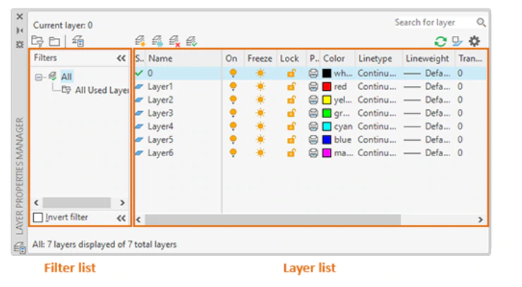
When you click the Layer Properties button, the program displays the Layer Properties Manager. Watch the video to learn more about controlling layer settings.

Here are the most commonly used layer settings in the Layer Properties Manager:

Turn off layers to reduce the visual complexity of your drawing while you work.

Layers icons in on and off states

Freeze layers that you do not need to access for a while.

Layer icons in frozen and unfrozen states

Lock layers when you want to prevent accidental changes to the objects on those layers.

<50 characters, sentence case, use keywords

Set default properties for each layer, including color, linetype, lineweight, and transparency.

Was this information helpful?