Understand modeling 1D river sediment
Any referenced datasets can be downloaded from "Module downloads" in the module overview.
Step-by-step guide
The currently available 1D erosion deposition models were not developed with fluvial environments in mind.
The behavior of sediments in these environments is more complex and requires additional features to assist in modeling.
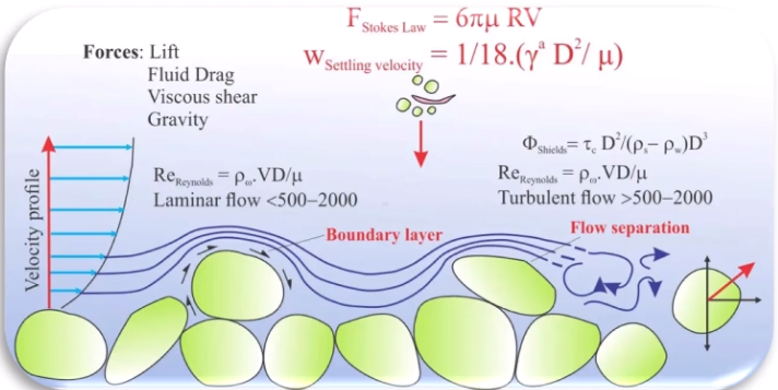
When performing 1D river modeling in InfoWorks ICM, assume the following:
- Suspended sediment is well mixed and evenly distributed within the flow.
- The deposition, based on settling velocity, depends on the particle diameter and the viscosity of the flow.
- Cohesive forces are ignored.
ICM supports three models for calculating river erosion and deposition.
- Ackers-White model: Based on non-dimensional carrying capacity.
- Velikanov model: Calculates two concentrations (Cmin and Cmax) for sediment erosion and deposition.
- KUL model: Determines two critical shear stress values (tau critical for deposition and tau critical for erosion).
River reach bed sediment
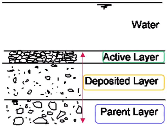
In river modeling, bed sediment is divided into three layers:
- The active layer at the riverbed surface
- The deposited layer beneath the surface
- The parent layer below the deposited layer
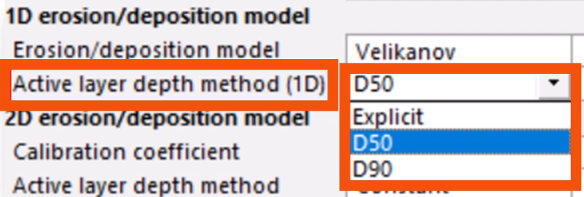
The active layer thickness is determined by the D50 or D90 bed material size multiplied by the active layer depth factor, or it can be set explicitly for each river reach.
As sediment is deposited in the active layer, an equal volume of material is transferred to the deposited layer. If the sediment deposited exceeds the active layer thickness, material is transferred directly to the deposited layer.
Only the deposited layer exchanges material with the parent layer.
As sediment is eroded from the active layer, an equal volume of material is transferred from the layer below—the deposited layer or the parent layer (if net erosion has occurred).
Material transferred is assumed to have the same composition as the layer from which it came.
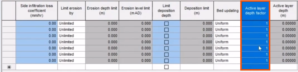
To set the active layer thickness:
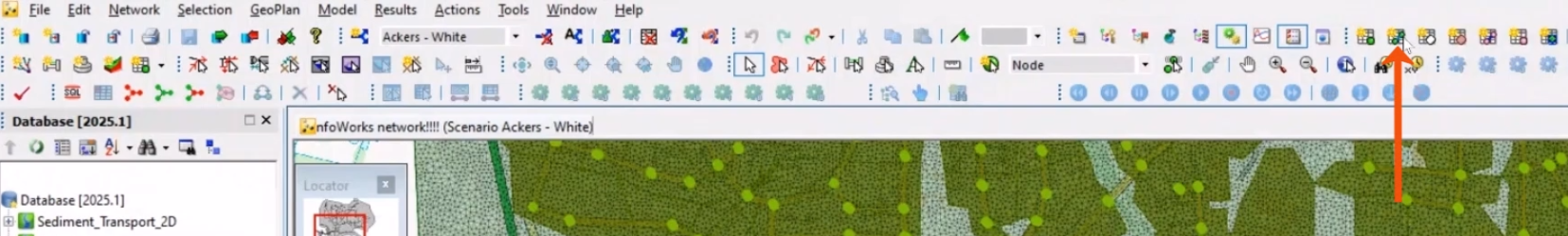
- From the Modeling Grid Windows toolbar, click New links window.
- In the grid window, scroll to and select the River reach tab.
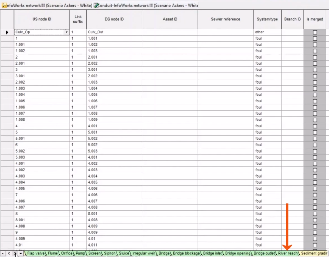
- In the Active layer depth factor column, define the value, which will be multiplied by the average diameter, D50 or D90.
The deposited layer contains material transferred from the active layer once it reaches its maximum thickness.
This layer can shrink to zero thickness if all of its material is transferred to the active layer.
The parent layer is the riverbed itself, characterized by its sediment grading.
Mass bed exchange
When setting up 1D erosion and deposition in fluvial environments, two parameters are crucial: the erosion limit and bed updating.
The erosion limit can be set by depth, level above datum, or a combination of both, or it can be set to allow unlimited erosion. This example focuses on unlimited bed erosion, where no depth threshold prevents erosion.
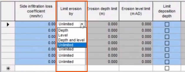
To set the erosion limit:
- On the River reach tab, locate the Limit erosion by column.
- Choose the option that best suits the case study. In this case, leave Unlimited selected.
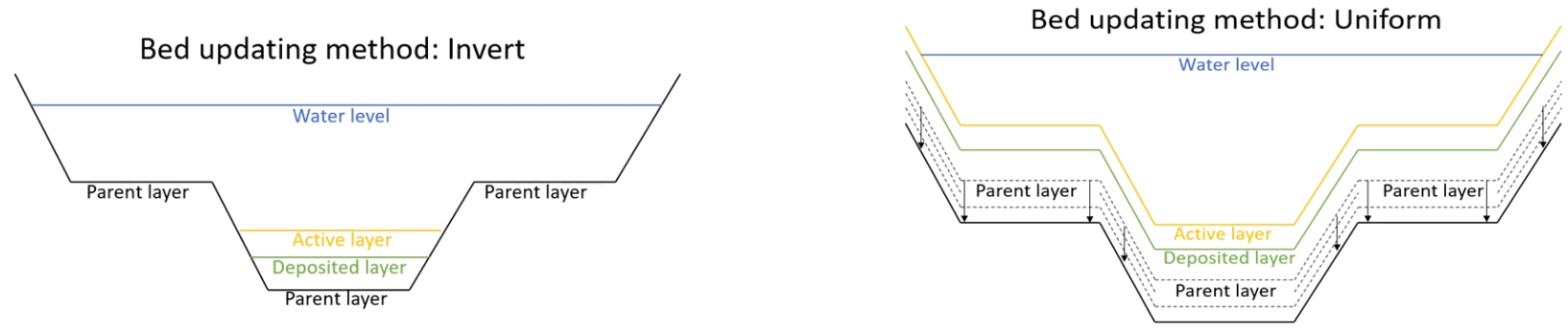
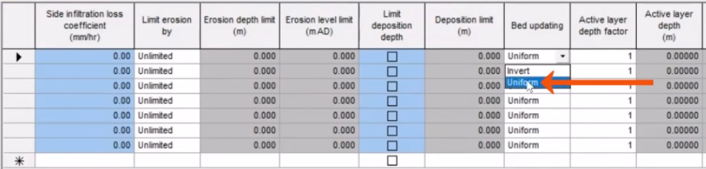
Bed updating can be achieved through either the invert or uniform method.
- The invert method involves sediment deposition and erosion from the invert of the channel, with no erosion of the original section. With this method, the erodible depth must be set to zero.
- The uniform method allows deposition and erosion uniformly across the section.
To set the method for bed updating:
- On the River reach tab, find the Bed updating column.
- For this example, select Uniform to represent erosion and deposition uniformly in the cross-section.
View the results of sedimentation in graphs, tables, or long section results.
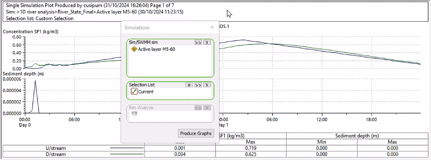
Note that, similar to pipe sediment, only the total sediment depth can be reported, graphed and viewed. The two sediment fractions cannot be graphed separately, and the various active, deposited, or bed sediment layers cannot be reported independently.