Set up 2D sediment initial conditions
Any referenced datasets can be downloaded from "Module downloads" in the module overview.
Step-by-step guide
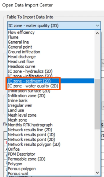
When simulating 2D sediment transport in InfoWorks ICM, a 2D initial conditions object is used to assign the relevant water quality values to 2D mesh elements within designated zone polygons.
Sediment zones define geographic areas where the initial sediment transport parameters will be applied.
Riverbeds often contain multiple sediment fractions, each with unique characteristics. Sediment fractions can be modeled independently, with no interactions, or dependently, interacting with each other.
Each fraction is defined by several properties:
- Porosity indicates the void space in the sediment and is important for water flow and sediment interaction.
- Density affects how sediment settles or remains suspended. It is typically measured in kilograms per cubic meter.
- Settling velocity determines when and where sediment will be deposited. There are multiple methods available to define it.

2D initial conditions can represent the suspended sediment concentration for each sediment fraction and can specify bed composition through the depth or elevation of each layer.
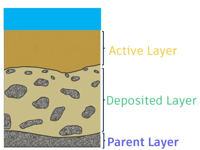
It is possible to specify several different sediment layers:
- The parent layer is above the non-erodible layer. It cannot grow and is only affected by erosion.
- A deposited layer grows or diminishes with deposition and erosion. It sits above the parent layer and begins to erode if the deposited layer erodes completely.
- The active layer is at the surface of the bed and represents the material that takes part in the erosion-deposition process.
To define the 2D initial conditions:
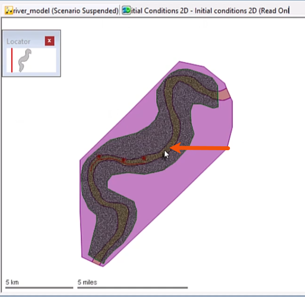
- Import or draw a polygon that covers the river reach and name it accordingly, such as “Sediment bed”.
- In the GeoPlan, select the 2D initial conditions object.
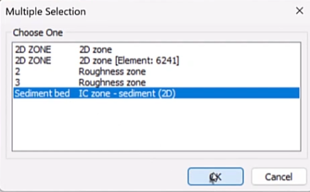
- In the Multiple Selection dialog, select Sediment bed IC zone.
- Click OK.
To set the conditions for the sediment layers:
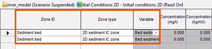
- Open the Initial conditions 2D grid window.
In this example, there is an active layer and a deposited layer.
- In the Zone ID field, enter the same ID used for the imported or created polygon, “Sediment bed”.
- For the Zone type, select 2D sediment IC zone.
- In the Variable column, select Bed sediment.
The Level type can be set to either Depth, which is the level relative to the ground, or Elevation, which is the level above a specified datum.
- In this case, for both layers, select Depth.
- Specify the two depths as 0.328 and 2.953.

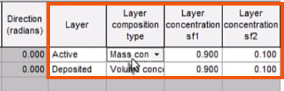
Layers can be defined as Non-erodible, Parent, Deposited, or Active.
- For this example, in the Layer column, set the first layer to Active.
- Set the second layer to Deposited.
The Layer composition type can be set to mass concentration, which is in kilograms per kilogram, or Volume concentration, which is in cubic meters per cubic meter.
- Here, for the first layer, select Mass concentration.
- For the second layer, select Volume concentration.
- Specify Layer concentration sf1 as 0.900.
- Specify Layer concentration sf2 as 0.100.
The initial conditions are set and will be applied at the start of the 2D simulation.