Adjusting preferences and tolerances in Robot
Any referenced datasets can be downloaded from "Module downloads" in the module overview.
Adjust preferences and tolerances in Robot - Exercise
In this practice, you will step through the process of setting recommended model generation and meshing parameters in Robot, changing local mesh settings, and modifying the tolerance of model generation.
- Open Autodesk Robot Structural Analysis Professional 2020.
- Open in it the project STRUCTURAL_before analysis.rtd.
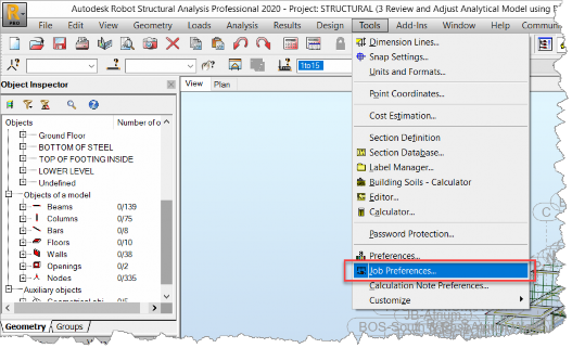
- Select Tools > Job Preferences… from the pull-down text menu.
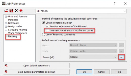
- The Job Preferences dialog box is opened. Select Meshing in the left panel and switch off Kinematic constraints in incoherent points. It will result in additional iterations to generate coherent FE mesh instead of using kinematic constraints to connect incoherent meshes. Select … next to Panels (all), as shown below.
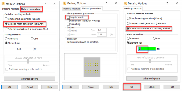
- The Meshing Options dialog box is opened. Activate Complex mesh generation (Delaunay). Then, in the Method parameters tab, switch off Regular mesh. After returning to the Meshing methods tab, activate Automatic selection of a meshing method and specify the Element size equal to 3 ft. Accept these changes with OK in the Meshing Options dialog box and in the Job Preferences dialog box.
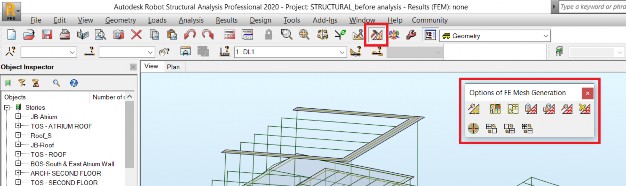
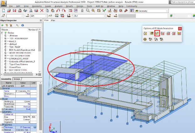
- Choose the icon marked below to open the Options of FE Mesh Generation toolbar.
- Make sure that the mouse cursor is in the selection mode. If the cursor over the graphic view is different than
 press the right mouse button to display the context menu, as displayed below, and choose Select.
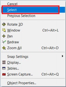
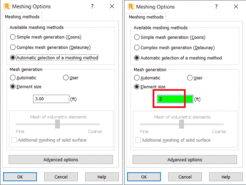
- Select the slab marked below and choose the Meshing Options icon from the Options of FE Mesh Generation toolbar. Slab can be selected hovering mouse cursor over its edge until the edge is highlighted and pressing the left mouse button.
- The Meshing Options dialog box is opened. Change the element size from the default size of 3 ft, set in the point 5. above, to 2 ft. This change is applicable to the selected panel.
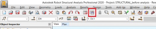
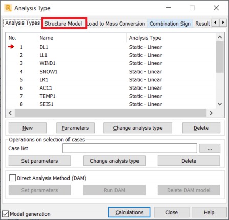
- Chose the Analysis Parameters icon marked below to open the Analysis Type dialog box.
- The Analysis Type dialog box is opened with the Analysis Types tab active, where load cases and combinations defined in the model are displayed. Select the Structure Model tab to access parameters related to model generation.
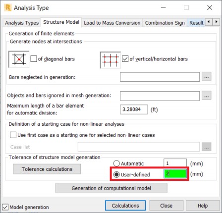
- The Structure Model tab of the Analysis Type dialog box is opened. Change from Automatic to User-defined tolerance of structure model generation and set the tolerance value equal to 2mm.
- Save the model with a new name using File > Save As… from the pull-down text menu.