& Construction

Integrated BIM tools, including Revit, AutoCAD, and Civil 3D
& Manufacturing

Professional CAD/CAM tools built on Inventor and AutoCAD
Integrated BIM tools, including Revit, AutoCAD, and Civil 3D
Professional CAD/CAM tools built on Inventor and AutoCAD
Any referenced datasets can be downloaded from "Module downloads" in the module overview.
Transcript
00:08
INSTRUCTOR: You can create construction details directly
00:10
from the model you already have, or you
00:13
can draw them as separate and independent drawings
00:15
and diagrams.
00:15
They can include both live 3D elements
00:18
and overlaid two-dimensional components.
00:21
You can even import and reuse standard details
00:25
from both Revit and AutoCAD.
00:27
So let's start with a simple typical construction detail.
00:30
It starts with view.
00:31
Let's go to the View tab.
00:33
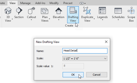
For this example, we're going to create a drafting view.
00:36
Now, a drafting view creates a simple 2D canvas
00:40
that you can place detailed components on.
00:43
So let's go to the Annotate tab, and we're
00:45
going to use this 2D detail component button here.
00:48
By default, we only have a few components
00:51
loaded into this file.
00:52
So let's go right to Load Family.
00:54
And then within our imperial library,
00:58
we're going to click the Detail Items folder.
01:01
The Detail Items folder is organized
01:03
into master spec divisions.
01:04
And we're going to start in the 09-Finishes folder,
01:07
then go to Plaster and Gypsum Board,
01:09
and then finally Gypsum Board.
01:11
And we'll import the Gypsum Wallboard in Section.
01:15
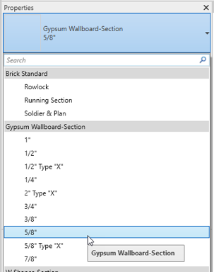
When you go to the Type Selector,
01:16
you'll see that that came in with several different sizes.
01:19
So let's choose the 5/8 size.
01:22
Click anywhere on screen to start drawing.
01:24
And this is a linear component so you
01:27
click two points to create it.
01:29
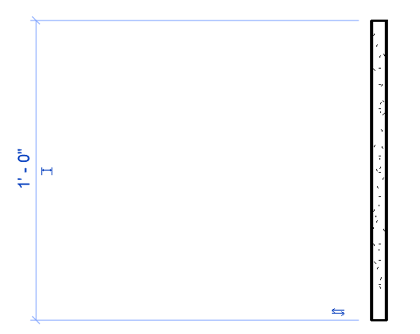
Let's draw a piece of drywall that's one foot long.
01:32
Click the Modify tool to cancel.
01:35
Right click and choose Zoom to Fit.
01:37
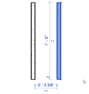
And then select this item and copy it next to itself
01:42
about four inches away.
01:44
And I'll roll the wheel back just to click and adjust
01:49
the Zoom accordingly.
01:50
Now, I'm going to repeat the process
01:52
and load in some additional 2D components.
01:55
So back to the Component tool, Load Family.
01:57
It'll remember the folder I was in previously,
01:59
so I'm going to back up a few steps to the main Detail Items
02:03
folder.
02:03
Next I'm going to go to the 05-Metals folder
02:07
and then to the Structural Metal Studs Framing folder
02:12
and then choose the C Studs in Section.
02:15
I'll open that up, and then I'll choose the 3 and 1/4 inch size.
02:19
And I'll place it approximately between the two
02:24
pieces of drywall.
02:25
I'll go right back to Load Family, back up a few steps.
02:29
And in the 08-Openings folder, I'll
02:32
then go to Metal Door Frames and then Hollow Metal Door Frames.
02:36
And then finally, choose the Double Revit Door Frame
02:39
in Section and click Open.
02:42
I'll change size to the 5 and 3/4,
02:46
and I'll place that approximately
02:48
where I need it to go.
02:49
One more component, Load Family again, go up a few steps,
02:53
go into the General folder, and bring in a break line.
02:56
And I'll place that approximately
02:58
where it needs to go and click the Modify tool.
03:01
Now I'm going to zoom in down here at the bottom,
03:03
select my stud, and use the arrow key on my keyboard
03:07
to just nudge it over slightly.
03:09
And then I'll do the same thing with that door frame.
03:12
Then I'll zoom back out, select the break line next.
03:15
And it has several little controls,
03:17
and I can use those to adjust the size of the break
03:22
symbol itself and the width of the overall component.
03:27
On the Detail Panel we have a detail line option.
03:31
I'll choose that next.
03:32
And then here we have several line styles.
03:35
I want to switch to the wide line style
03:38
and start drawing right about here and draw out to the side.
03:43
Press Escape once to break the chain
03:45
and start drawing a second one and off to the side.
03:48
And those will represent where my ceiling line is.
03:51
I'll click Modify to cancel, and then let's add some insulation.
03:55
So there is a dedicated Insulation tool right here.
03:58
I want to reduce the width of that to about three inches.
04:02
Start right here at the middle of the stud
04:04
and pull it straight up and past the break line.
04:08
Now, that puts it right on top of the break line.
04:10
So I'll select the break line and use the Bring-to-Front tool
04:14
to bring the break line on top of the insulation.
04:18
Now, you can fine tune the graphics a little bit more
04:21
if you like and add additional components.
04:24
But now I'm going to move on to the Text tool
04:27
and just add some really basic notes to this detail.
04:31
So the Text tool is here on the Annotate tab,
04:33
or you can type TX.
04:35
Over here on the type selector I want to choose the 3/32-inch
04:39
aerial type.
04:41
And then in the Leader panel here
04:43
you have several leader options.
04:45
I want to make sure I'm choosing the two-segment leader.
04:47
Click your first point where you want the arrow
04:49
head of the leader to go.
04:51
Draw the first segment of the leader line.
04:53
Draw a small little elbow.
04:55
And with your third click, you will be in text edit mode.
04:59
To finish the note, you click next to it
05:01
in empty white space.
05:02
Don't press Enter.
05:04
Now stay in the text command and add any additional notes
05:07
that you would like to include.
05:10
And when you're done, it might look something like this.
05:13
Let's move on to importing an existing detail that you might
05:16
already have in your system.
05:18
So if you've created details previously in another project
05:21
and you want to reuse them, it's as
05:23
simple as going to the Insert tab
05:25
and using the Insert From File dropdown.
05:28
Choose Insert Views from a file, and then
05:31
browse to the location of the file that you want to insert.
05:35
Select the file and click Open.
05:37
Any views that are available in that project will be listed.
05:41
I have only one in this case.
05:42
Make sure it's checked, and then click OK.
05:46
You'll get a confirmation dialogue
05:48
about some duplicate types.
05:49
You can click OK again, and then that
05:51
will import this drafting view and its detail.
05:55
And it's just that easy to reuse an existing detail.
05:59
Now, you may also want to reuse details from outside
06:03
of Revit-- say, AutoCAD.
06:04
To do that is fairly simple as well.
06:07
Now, let's start with another drafting view for that.
06:11
Then on the Insert tab click the Link CAD button.
06:15
Here, I'll select this Detail file.
06:18
And I'll click Open, and then I'll
06:20
right click anywhere and choose Zoom to Fit.
06:23
Now, you'll see that this file preserved its colors
06:27
and does not contain any line weights.
06:30
We can do a little bit better.
06:32
We might want to customize the way that this
06:34
imported a little bit.
06:36
To do that, we'll select the file.
06:38
And it's currently pinned, so we're going to unpin it.
06:41
And then we'll be able to delete it.
06:43
And what I want to do is modify a few of those import settings
06:47
before importing it, and you'll see that the results come in
06:50
quite differently.
06:51
So on the Import panel there's a small dialog launcher button
06:54
right here.
06:55
So I click this Load button right here,
06:57
and I've got this file called Lineweights.
06:59
And when I open that up it will change this mapping table
07:03
to use different numbers for each
07:06
of the colors within the AutoCAD file.
07:08
So you match up the colors from the AutoCAD file
07:12
to appropriate line weights on the Revit side,
07:15
and then you click OK.
07:16
Then I'll repeat the Link CAD process, select the detail,
07:20
and this time I'll make a few changes.
07:23
I'm going to force all the colors to black and white.
07:25
And I want to make sure it comes in in the correct units,
07:28
so I'm going to choose millimeter and then click Open.
07:31
I'll right click and do Zoom to Fit again,
07:34
and you'll see that the detail comes in quite differently
07:36
this time.
07:37
The line weights don't look so well.
07:39
They're a little overpowering, and that really
07:41
has to do with setting an appropriate scale.
07:44
So I'm going to open up the Scale pop-up here and choose
07:48
six inch equals a foot.
07:49
And then you'll see that the detail now looks much better.
07:53
So whether or not you're drawing the details directly in Revit,
07:56
reusing existing Revit details, or bringing them
07:59
in from outside sources like CAD, you have lots of ways
08:02
that you can add construction details to your projects.
Video transcript
00:08
INSTRUCTOR: You can create construction details directly
00:10
from the model you already have, or you
00:13
can draw them as separate and independent drawings
00:15
and diagrams.
00:15
They can include both live 3D elements
00:18
and overlaid two-dimensional components.
00:21
You can even import and reuse standard details
00:25
from both Revit and AutoCAD.
00:27
So let's start with a simple typical construction detail.
00:30
It starts with view.
00:31
Let's go to the View tab.
00:33
For this example, we're going to create a drafting view.
00:36
Now, a drafting view creates a simple 2D canvas
00:40
that you can place detailed components on.
00:43
So let's go to the Annotate tab, and we're
00:45
going to use this 2D detail component button here.
00:48
By default, we only have a few components
00:51
loaded into this file.
00:52
So let's go right to Load Family.
00:54
And then within our imperial library,
00:58
we're going to click the Detail Items folder.
01:01
The Detail Items folder is organized
01:03
into master spec divisions.
01:04
And we're going to start in the 09-Finishes folder,
01:07
then go to Plaster and Gypsum Board,
01:09
and then finally Gypsum Board.
01:11
And we'll import the Gypsum Wallboard in Section.
01:15
When you go to the Type Selector,
01:16
you'll see that that came in with several different sizes.
01:19
So let's choose the 5/8 size.
01:22
Click anywhere on screen to start drawing.
01:24
And this is a linear component so you
01:27
click two points to create it.
01:29
Let's draw a piece of drywall that's one foot long.
01:32
Click the Modify tool to cancel.
01:35
Right click and choose Zoom to Fit.
01:37
And then select this item and copy it next to itself
01:42
about four inches away.
01:44
And I'll roll the wheel back just to click and adjust
01:49
the Zoom accordingly.
01:50
Now, I'm going to repeat the process
01:52
and load in some additional 2D components.
01:55
So back to the Component tool, Load Family.
01:57
It'll remember the folder I was in previously,
01:59
so I'm going to back up a few steps to the main Detail Items
02:03
folder.
02:03
Next I'm going to go to the 05-Metals folder
02:07
and then to the Structural Metal Studs Framing folder
02:12
and then choose the C Studs in Section.
02:15
I'll open that up, and then I'll choose the 3 and 1/4 inch size.
02:19
And I'll place it approximately between the two
02:24
pieces of drywall.
02:25
I'll go right back to Load Family, back up a few steps.
02:29
And in the 08-Openings folder, I'll
02:32
then go to Metal Door Frames and then Hollow Metal Door Frames.
02:36
And then finally, choose the Double Revit Door Frame
02:39
in Section and click Open.
02:42
I'll change size to the 5 and 3/4,
02:46
and I'll place that approximately
02:48
where I need it to go.
02:49
One more component, Load Family again, go up a few steps,
02:53
go into the General folder, and bring in a break line.
02:56
And I'll place that approximately
02:58
where it needs to go and click the Modify tool.
03:01
Now I'm going to zoom in down here at the bottom,
03:03
select my stud, and use the arrow key on my keyboard
03:07
to just nudge it over slightly.
03:09
And then I'll do the same thing with that door frame.
03:12
Then I'll zoom back out, select the break line next.
03:15
And it has several little controls,
03:17
and I can use those to adjust the size of the break
03:22
symbol itself and the width of the overall component.
03:27
On the Detail Panel we have a detail line option.
03:31
I'll choose that next.
03:32
And then here we have several line styles.
03:35
I want to switch to the wide line style
03:38
and start drawing right about here and draw out to the side.
03:43
Press Escape once to break the chain
03:45
and start drawing a second one and off to the side.
03:48
And those will represent where my ceiling line is.
03:51
I'll click Modify to cancel, and then let's add some insulation.
03:55
So there is a dedicated Insulation tool right here.
03:58
I want to reduce the width of that to about three inches.
04:02
Start right here at the middle of the stud
04:04
and pull it straight up and past the break line.
04:08
Now, that puts it right on top of the break line.
04:10
So I'll select the break line and use the Bring-to-Front tool
04:14
to bring the break line on top of the insulation.
04:18
Now, you can fine tune the graphics a little bit more
04:21
if you like and add additional components.
04:24
But now I'm going to move on to the Text tool
04:27
and just add some really basic notes to this detail.
04:31
So the Text tool is here on the Annotate tab,
04:33
or you can type TX.
04:35
Over here on the type selector I want to choose the 3/32-inch
04:39
aerial type.
04:41
And then in the Leader panel here
04:43
you have several leader options.
04:45
I want to make sure I'm choosing the two-segment leader.
04:47
Click your first point where you want the arrow
04:49
head of the leader to go.
04:51
Draw the first segment of the leader line.
04:53
Draw a small little elbow.
04:55
And with your third click, you will be in text edit mode.
04:59
To finish the note, you click next to it
05:01
in empty white space.
05:02
Don't press Enter.
05:04
Now stay in the text command and add any additional notes
05:07
that you would like to include.
05:10
And when you're done, it might look something like this.
05:13
Let's move on to importing an existing detail that you might
05:16
already have in your system.
05:18
So if you've created details previously in another project
05:21
and you want to reuse them, it's as
05:23
simple as going to the Insert tab
05:25
and using the Insert From File dropdown.
05:28
Choose Insert Views from a file, and then
05:31
browse to the location of the file that you want to insert.
05:35
Select the file and click Open.
05:37
Any views that are available in that project will be listed.
05:41
I have only one in this case.
05:42
Make sure it's checked, and then click OK.
05:46
You'll get a confirmation dialogue
05:48
about some duplicate types.
05:49
You can click OK again, and then that
05:51
will import this drafting view and its detail.
05:55
And it's just that easy to reuse an existing detail.
05:59
Now, you may also want to reuse details from outside
06:03
of Revit-- say, AutoCAD.
06:04
To do that is fairly simple as well.
06:07
Now, let's start with another drafting view for that.
06:11
Then on the Insert tab click the Link CAD button.
06:15
Here, I'll select this Detail file.
06:18
And I'll click Open, and then I'll
06:20
right click anywhere and choose Zoom to Fit.
06:23
Now, you'll see that this file preserved its colors
06:27
and does not contain any line weights.
06:30
We can do a little bit better.
06:32
We might want to customize the way that this
06:34
imported a little bit.
06:36
To do that, we'll select the file.
06:38
And it's currently pinned, so we're going to unpin it.
06:41
And then we'll be able to delete it.
06:43
And what I want to do is modify a few of those import settings
06:47
before importing it, and you'll see that the results come in
06:50
quite differently.
06:51
So on the Import panel there's a small dialog launcher button
06:54
right here.
06:55
So I click this Load button right here,
06:57
and I've got this file called Lineweights.
06:59
And when I open that up it will change this mapping table
07:03
to use different numbers for each
07:06
of the colors within the AutoCAD file.
07:08
So you match up the colors from the AutoCAD file
07:12
to appropriate line weights on the Revit side,
07:15
and then you click OK.
07:16
Then I'll repeat the Link CAD process, select the detail,
07:20
and this time I'll make a few changes.
07:23
I'm going to force all the colors to black and white.
07:25
And I want to make sure it comes in in the correct units,
07:28
so I'm going to choose millimeter and then click Open.
07:31
I'll right click and do Zoom to Fit again,
07:34
and you'll see that the detail comes in quite differently
07:36
this time.
07:37
The line weights don't look so well.
07:39
They're a little overpowering, and that really
07:41
has to do with setting an appropriate scale.
07:44
So I'm going to open up the Scale pop-up here and choose
07:48
six inch equals a foot.
07:49
And then you'll see that the detail now looks much better.
07:53
So whether or not you're drawing the details directly in Revit,
07:56
reusing existing Revit details, or bringing them
07:59
in from outside sources like CAD, you have lots of ways
08:02
that you can add construction details to your projects.
In Revit, you can create construction details directly from the model you already have or you can draw them as separate and independent drawings and diagrams. They can include both live 3D elements and overlaid two-dimensional components. You can even import and reuse standard details from AutoCAD to leverage libraries already in use in your firm’s workflow.
Catch-up file completed to this point: 17_Medical Center_Details.rvt
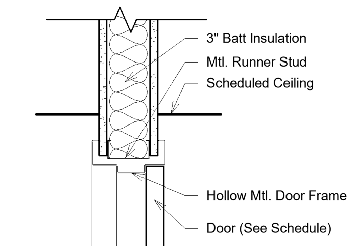
Let’s create a simple “typical” construction detail. It starts with a view.
Figure 17–1 Create a new Drafting View
A Drafting View is a simple blank 2D canvas where you can draw any detail or diagram you like. It is not linked to the 3D model.
Figure 17–2 Create a Detail Component
Like 3D families, 2D detail item families have types. Notice the various sizes (types) of drywall that were imported with this family.
Figure 17–3 Choose a predefined size from the Type Selector
Figure 17–4 Draw a vertical piece of drywall
Figure 17–5 Copy the drywall component
All the standard Revit modification tools can help you compose your detail. Use Move, Align and any other tools as required. Note in the figure that the break line component has shape handles to adjust its size.
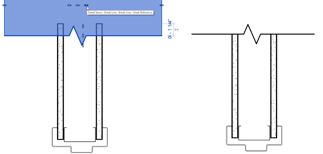
Figure 17–6 Adjust component placement
Figure 17–7 The Detail Line tool
Figure 17–8 Choose the Wide Lines line style
Figure 17–9 The Insulation tool
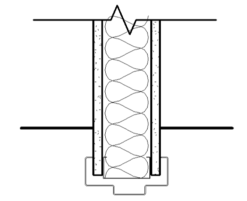
Figure 17–10 Add insulation and lines to represent the ceiling
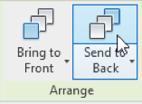
Notice that the insulation appears in front of the break line.
Figure 17–11 Send the insulation to the back
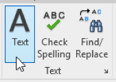
To finish the detail, add some annotation.
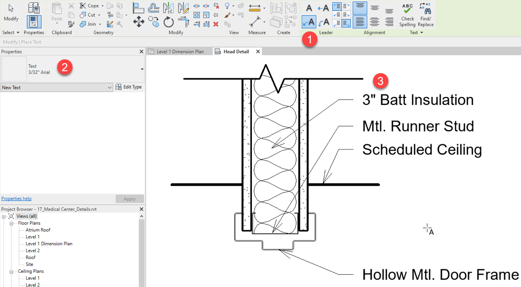
Figure 17–12 The Text Notes tool
Figure 17–13 Run the text tool, configure options and begin typing
Figure 17–14 Add additional lines and text to finish the detail
In addition to drawing details from scratch, you can also reuse them from other projects.
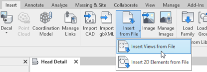
Figure 17–15 Insert a detail view from another file
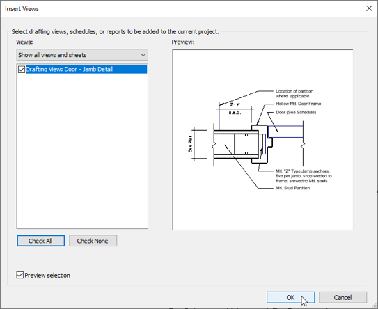
This file contains only one detail. But you can include several details in a single file and then import them in a single step.
Figure 17–16 Select the detail(s) to import and then click OK
This process makes it easy to reuse views, but please note that this works with 2D views only.
Figure 17–17The Link CAD tool
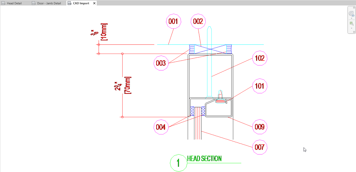
Figure 17–18 Link in a CAD file to use as a detail
This is a simple storefront detail downloaded from the Internet. Notice that the results are not that great. There are many options available to help Revit correctly interpret the CAD data being imported.
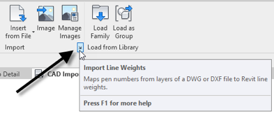
Figure 17–19 We can customize the way that colors from a CAD file match to Revit line weights
If you prefer, you can use the Load button and load the saved version of this file instead: Lineweights.txt.
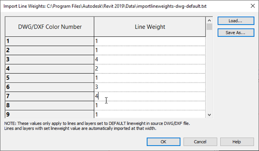
Figure 17–20 Edit the Color to Line Weight mapping table
Figure 17–21 Change the color and units settings before linking
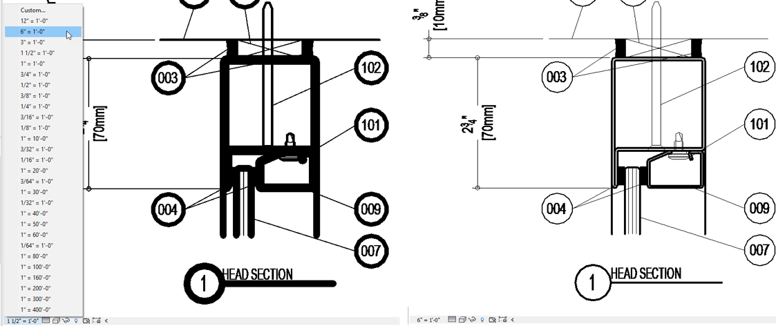
Notice that this time the file’s lines are all black and they are also using line weights. This detail is very small however, so the line weights look too heavy. Let’s adjust the scale to fix this.
Figure 17–22Change the view scale to make the line weights display better
Note that the line weights adjust with the change in scale.
Revit has many kinds of views: 2D views, 3D views, graphical and non-graphical views. Schedules are non-graphical views that list a collection of related elements and their various properties. They are presented in a form that is similar to a spreadsheet. Schedules can be used for reporting and for editing the model.
Catch-up file completed to this point: 18_Medical Center_Schedules.rvt
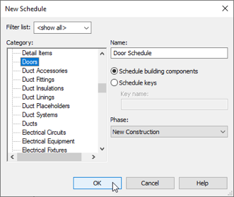
Schedules can be created from nearly any category. Let’s make a simple Door Schedule.
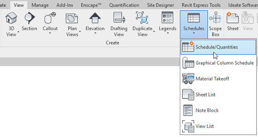
Figure 18–1 Create a new schedule view
Figure 18–2 Create a Door Schedule
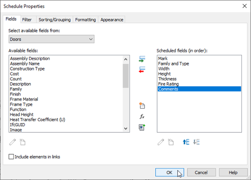
The next dialog will display a list of properties that are available for the Doors category. You can add one or several to the schedule. Select the one(s) you wish to add and either double-click them or use the small green arrow in the middle to add them to the schedule.
Figure 18–3 Choose the fields that you want to include in the schedule
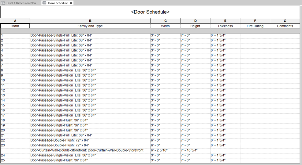
Figure 18–4 The schedule view as it appears onscreen
You can click and drag between columns to resize them. Use the ctrl key and the mouse wheel to zoom in or out.
Notice that all doors in the model are listed in this table. They each display their respective sizes and mark values (number).
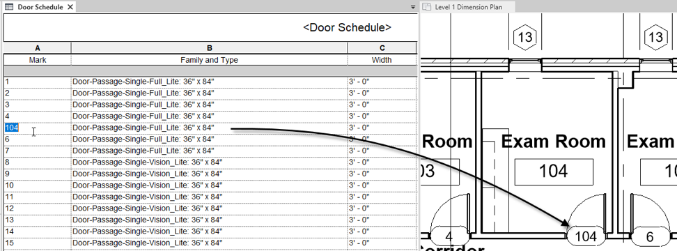
Figure 18–5 Selections made in schedule also highlihgt in other views
Figure 18–6 Changing a value in the schedule updates in other views as well
This works both ways. If you select a door in the plan and make an edit, it will be reflected in the schedule as well.
Figure 18–7 Changes made in the model immediately appear in the schedule as well
Schedules can be a great way to query your model to explore quantities and other useful project-wide insights.
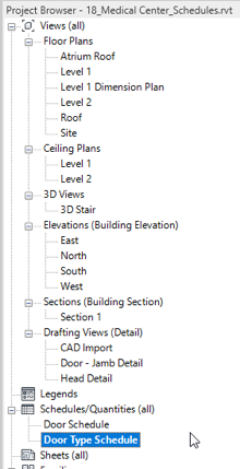
Figure 18–8 Create a duplicate of the door schedule
Figure 18–9 Add the type Mark field
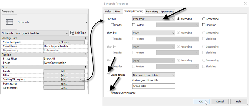
Figure 18–10 Add a sort criterion, totals and disable itemizing
This version of the schedule shows the same collection of doors, but since we adjusted the sorting and grouping, it is telling a very different story. The first schedule tells us useful information about each individual door. This version tells us how many kinds of doors we are using and how many of each type we have (see Figure 18–11).
Figure 18–11 Each schedule can sort group and summarize the information it displays differently from other views
While working in Revit it is common for you to have to access information from other programs such as AutoCAD. We saw an example of this in the previous exercise. But standard details are not the only time that it is useful to work with CAD files in Revit. There are many scenarios where other you might be collaborating with will be using a program other than Revit. Revit both reads and writes DWG files and other common formats as well. So this make collaboration with other disciplines much easier.
How to buy
Privacy | Do not sell or share my personal information | Cookie preferences | Report noncompliance | Terms of use | Legal | © 2025 Autodesk Inc. All rights reserved
Sign in to start learning
Sign in for unlimited free access to all learning content.Save your progress
Take assessments
Receive personalized recommendations
May we collect and use your data?
Learn more about the Third Party Services we use and our Privacy Statement.May we collect and use your data to tailor your experience?
Explore the benefits of a customized experience by managing your privacy settings for this site or visit our Privacy Statement to learn more about your options.